Chrysler Le Baron, Dodge Dynasty, Plymouth Acclaim. Manual - part 186


  Index      Chrysler     Chrysler Le Baron, Dodge Dynasty, Plymouth Acclaim - service repair manual 1993 year


Search            


Content   ..  184  185  186  187   ..


Chrysler Le Baron, Dodge Dynasty, Plymouth Acclaim. Manual - part 186


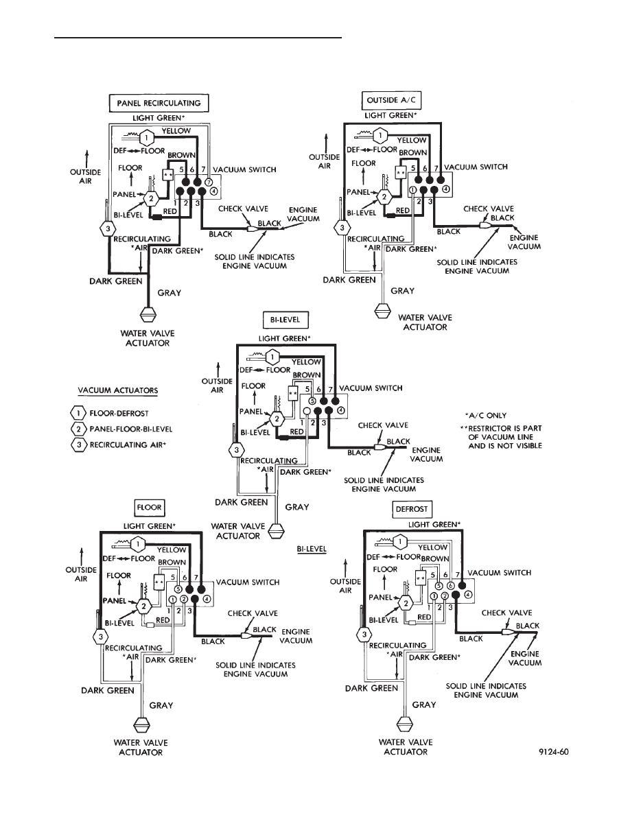
VACUUM CIRCUITS—HEATER OR HEATER A/C CONTROL

Ä

HEATING AND AIR CONDITIONING

24 - 5

HEATER AND A/C PERFORMANCE TESTS

HEATER OUTPUT TEST

PRE-DIAGNOSTIC PREPARATIONS

Review Safety Precautions and Warnings before

performing the following procedures.

Check the radiator coolant level, drive belt tension,

and engine vacuum line connections. Also check ra-
diator air flow and radiator fan operation. Start en-
gine and allow to warm up to normal operating
temperature.

WARNING:

DO

NOT

REMOVE

RADIATOR

CAP

WHEN ENGINE IS HOT, PERSONAL INJURY CAN
RESULT.

If vehicle has been run recently, wait 15 minutes

before removing cap. Place a rag over the cap and
turn it to the first safety stop. Allow pressure to es-
cape through the overflow tube. When the system
stabilizes, remove the cap completely.

MAXIMUM HEATER OUTPUT: TEST AND
ACTION

Engine coolant is provided to the heater system by

two 16 mm (5/8 inch inside diameter) heater hoses.
With engine idling at normal running temperature,
set the control to maximum heat, floor, and high
blower setting. Using a test thermometer, check the
air temperature coming from the floor outlets, refer
to Temperature Reference chart.

If the floor outlet air temperature is low, refer to

Group 7, Cooling System for coolant temperature
specifications. Both heater hoses should be HOT to
the touch. The coolant return hose should be slightly
cooler than the supply hose. If coolant return hose is
much cooler than the supply hose, locate and repair
engine coolant flow obstruction in heater system.

POSSIBLE LOCATIONS OR CAUSE OF OBSTRUCTED
COOLANT FLOW

(a) Pinched or kinked heater hoses.
(b) Improper heater hose routing.

(c) Plugged heater hoses or supply and return

ports at cooling system connections, refer to Group
7, Cooling System.

(d) Plugged heater core.

If proper coolant flow through heater system is ver-

ified and outlet air temperature is still low, a me-
chanical problem may exist.

POSSIBLE LOCATION OR CAUSE OF INSUFFICIENT HEAT

(a) Obstructed cowl air intake.
(b) Obstructed heater system outlets.
(c) Blend-air door not functioning properly.

TEMPERATURE CONTROL

If temperature cannot be adjusted with the TEMP

lever on the control panel, or TEMP lever is difficult
to move, the following could require service:

(a) Blend-air door binding.
(b) Control cables miss-routed, pinched, kinked,

or disconnected.

(c) Improper engine coolant temperature.

A/C PERFORMANCE TEST

The air conditioning system is designed to remove

heat and humidity from the air entering the passen-
ger compartment. The evaporator, located in the
heater A/C unit behind the instrument panel, is
cooled to temperatures near the freezing point. As
warm damp air passes over the fins in the evapora-
tor, moisture in the air condenses to water, dehumid-
ifying the air. Condensation on the evaporator fins
reduces the evaporators ability to absorb heat. Dur-
ing periods of high heat and humidity an A/C system
will be less effective than during periods of high heat
and low humidity. With the instrument control set to
RECIRC, only air from the passenger compartment
passes through the evaporator. As the passenger
compartment air dehumidifies, A/C performance lev-
els rise.

PERFORMANCE TEST PROCEDURE

Review Safety Precautions and Warnings before

proceeding with this procedure. Air temperature in
test room and on vehicle must be 70°F (21°C) mini-
mum for this test.

(1) Connect a tachometer and manifold gauge set.
(2) Set control to A/C, RECIRC, PANEL, or MAX

A/C, temperature lever on full cool and blower on
high.

(3) Start engine and hold at 1000 rpm with A/C

clutch engaged.

(4) Engine should be warmed up with doors and

windows closed.

TEMPERATURE REFERENCE CHART

24 - 6

HEATING AND AIR CONDITIONING

Ä

(5) Insert a thermometer in the left center A/C

outlet and operate the engine for five minutes. The
A/C clutch may cycle depending on ambient condi-
tions.

(6) With the A/C clutch engaged, compare the dis-

charge air temperature to the A/C Performance Tem-
peratures chart.

(7) If the discharge air temperature is low, refer to

the Diagnostic Analysis Charts in this Group.

A/C PERFORMANCE TEMPERATURES

Ä

HEATING AND AIR CONDITIONING

24 - 7

REFRIGERANT SERVICE PROCEDURES

INDEX

page

page

Adding Partial Refrigerant Charge

. . . . . . . . . . . . 10

Charging Refrigerant System—Empty System

. . . 11

Discharging Refrigerant System

. . . . . . . . . . . . . . 11

Evacuating Refrigerant System

. . . . . . . . . . . . . . 11

Manifold Gauge Set Connections

. . . . . . . . . . . . . 9

Oil Level

. . . . . . . . . . . . . . . . . . . . . . . . . . . . . . . 12

R-12 Refrigerant Equipment

. . . . . . . . . . . . . . . . . 8

Refrigerant Recycling

. . . . . . . . . . . . . . . . . . . . . . 9

Sight Glass Refrigerant Level Inspection

. . . . . . . . 8

Testing for Refrigerant Leaks

. . . . . . . . . . . . . . . 10

SIGHT GLASS REFRIGERANT LEVEL INSPECTION

The filter-drier is equipped with a sight glass (Fig.

1) that is used as a refrigerant level indicator only.
This sight glass is not to be used for A/C perfor-
mance testing. 
To check the refrigerant level re-
move the vehicle jack. Then clean the sight glass,
start and warm up engine, and hold rpm slightly
above idle (1100 rpm). Place the air conditioning con-
trol on A/C, RECIRC and high blower. The work
area should be at least 21°C (70°F). If a Fixed Dis-
placement type compressor does not engage, the re-
frigerant level is probably too low for the Low
Pressure Cut-Off switch to detect. Or, with a Vari-
able Displacement compressor, for the Differential
Pressure Cut-off to detect. If compressor clutch does
not engage, test the refrigerant system for leaks. If
compressor clutch engages, allow approximately one
minute for refrigerant to stabilize. View refrigerant
through sight glass. The suction line should be cold
to the touch and the sight glass should be clear.

If foam or bubbles are visible in sight glass, the re-

frigerant level is probably low. Occasional foam or
bubbles are normal when the work area temperature
is above 43°C (110°F) or below 21°C (70°F). If suction
line is cold and occasional bubbles are visible in the
sight glass, block the condenser air flow. This will in-
crease the compressor discharge pressure. Do not al-
low engine to over heat. 
Bubbles should dissipate.
If not, the refrigerant level is low.

CAUTION: Do not allow engine to over heat while
blocking the condenser air flow.

WARNING: R-12 REFRIGERANT IS DETRIMENTAL
TO THE ENVIRONMENT WHEN RELEASED TO THE
ATMOSPHERE. DO NOT ADD R-12 REFRIGERANT
TO A SYSTEM THAT HAS A KNOWN LEAK.

The refrigerant system will not be low on (R-12)

unless there is a leak. Find and repair the leak be-
fore charging.

R-12 REFRIGERANT EQUIPMENT

WARNING: EYE PROTECTION MUST BE USED
WHEN SERVICING AN AIR CONDITIONING REFRIG-
ERANT SYSTEM. TURN OFF (ROTATE CLOCKWISE)
ALL VALVES ON THE EQUIPMENT BEING USED
BEFORE PROCEEDING WITH THIS OPERATION.
PERSONNEL INJURY CAN RESULT.

When servicing an air conditioning system, an A/C

charging station is recommended (Fig. 2). An (R-12)
refrigerant recovery/recycling device (Fig. 3) should
also be used. This device should meet SAE standards.
Contact an automotive service equipment supplier
for refrigerant recycling/recovering equipment. Refer
to the operating instructions provided with the
equipment for proper operation.

A manifold gauge set (Fig. 4) must also be used in

conjunction with the charging and/or recovery/recy-
cling device. The service hoses on the gauge set be-
ing used should have manual (turn wheel) or
automatic back flow valves at the service port con-
nector ends. This will prevent refrigerant from being
release into the atmosphere.

Fig. 1 Filter Drier and Sight Glass

24 - 8

HEATING AND AIR CONDITIONING

Ä


Content   ..  184  185  186  187   ..