Chrysler Le Baron, Dodge Dynasty, Plymouth Acclaim. Manual - part 184
(3) Separate buckle/belt assembly from vehicle.
INBOARD BUCKLE/CENTER OCCUPANT BELT
INSTALLATION
Reverse the preceding operation.
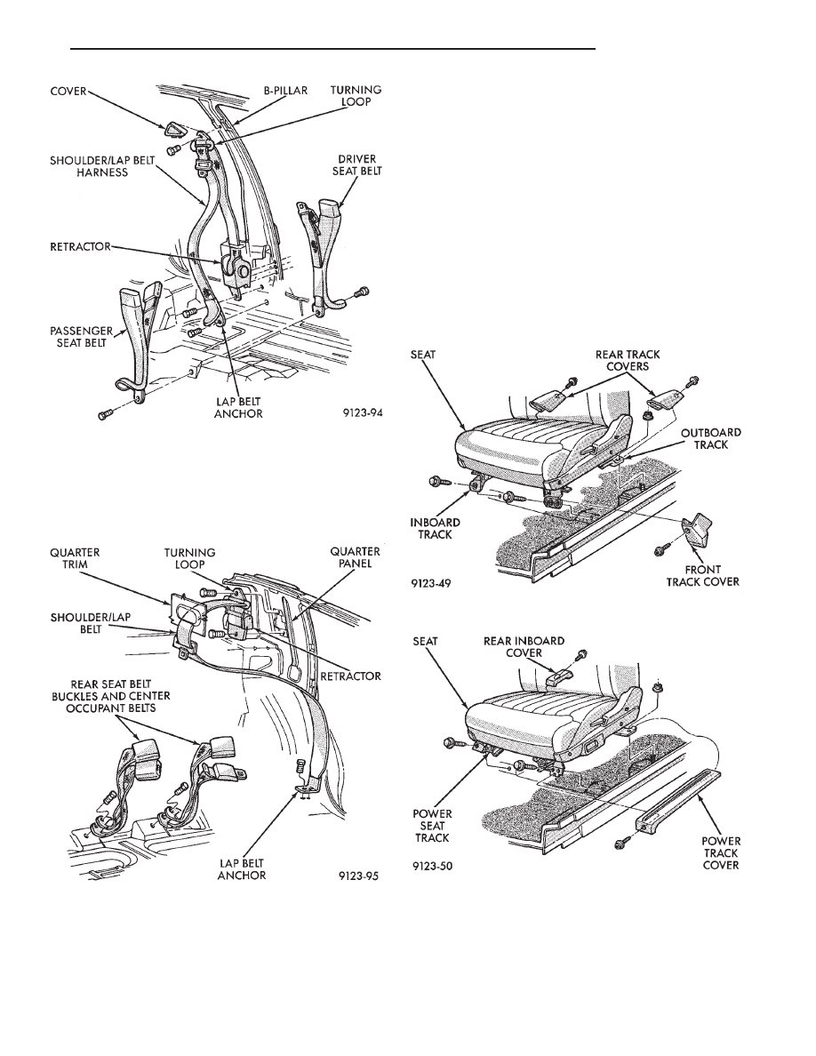
FRONT SEATS
REMOVAL (FIG. 28 OR 29)
(1) Position seat full forward.
(2) Remove screws holding rear track riser covers
and separate covers from tracks.
(3) On power seat track, remove outboard track
cover.
(4) Remove inboard seat belt attaching bolt from
floor.
(5) Remove nuts holding seat track to floor.
(6) Position seat full rearward.
(7) Remove door sill scuff plate and disconnect
power seat track wire connector.
(8) Remove bolts holding seat track to cross mem-
ber.
(9) Remove seat from vehicle.
INSTALLATION
Reverse the preceding operation.
REAR SEATS
REAR SEAT CUSHION REMOVAL
(1) Remove bolts holding cushion to floor.
(2) Disconnect center occupant seat belts from
cushion.
Fig. 26 Front Seat Belts
Fig. 27 Rear Seat Belts
Fig. 28 Manual Front Seat—Typical
Fig. 29 Power Front Seat—Typical
Ä
AY-BODY
23 - 145