Chrysler Le Baron, Dodge Dynasty, Plymouth Acclaim. Manual - part 181
AY-VEHICLE BODY COMPONENT SERVICE
INDEX
page
page
A-Pillar and Roof Rail Mouldings
. . . . . . . . . . . . . . . . . . . . . . 143
. . . . . . . . . . . . . . . . . . . . . . . . . 146
Cowl Panel Trim and Scuff Plates
. . . . . . . . . . . . . . . . 137
. . . . . . . . . . . . . . . . . . . . 137
. . . . . . . . . . . . . . . . . . . . . . . . 139
. . . . . . . . . . . . . . . . . . . . . . . . 138
Front Door Silencer and Water Shield
. . . . . . . . . . . . . . . . . . . . 136
. . . . . . . . . . . . . . 138
. . . . . . . . . . . . . . . . . 136
. . . . . . . . . . . . . . . . . . . . . . . . 144
. . . . . . . . . . . . . . . . . . . . . . . . . . . . 145
. . . . . . . . . . . . . . . . . . . . . . . . 133
. . . . . . . . . . . . . . . . . . . . . . . . 133
Grille Opening Panel AY/P Body
Grille Opening Panel AY/S Body
. . . . . . . . . . . . . . . . . . . . . . . . . . . . 142
. . . . . . . . . . . . . . . . . . . . . . . 134
. . . . . . . . . . . . . . . . . . 134
. . . . . . . . . . . . . . . . . . . . . 138
. . . . . . . . . . . . . . . . . . . . . . . 142
. . . . . . . . . . . . . . . . . . . . . . 143
. . . . . . . . . . . . . . . . . . . 146
. . . . . . . . . . . . . . . . . . . . 140
Rear Door Fixed Glass Outer Cover
. . . . . . . . . . . . . . . . . . . . . . . . . 141
. . . . . . . . . . . . . . . . . . . . . . . . 141
Rear Door Glass Lift Plate and Guide Bar
. . . . . . . . . . . . . . . . . . . . . . . . 140
Rear Door Outer Cover—AY-P Body
. . . . . . . . . . . . . . . . 140
Rear Door Silencer and Water Shield
. . . . . . . . . . . . . . . . . . . . 139
. . . . . . . . . . . . . . 141
. . . . . . . . . . . . . . . . . . . . . . . . . 144
. . . . . . . . . . . . . . . . . . . . . . . . . . . . 145
. . . . . . . . . . . . . . . . . . . . 144
. . . . . . . . . . . . . . . . . . . . . . 147
. . . . . . . . . . . . . . . 137
. . . . . . . . . . . . . . . . . . . . . . . . . . . . . . 147
. . . . . . . . . . . . . . . . . . . . . . . . 147
. . . . . . . . . . . . . . . . . . . . 148
. . . . . . . . . . . . . . . . . . . . . . . 146
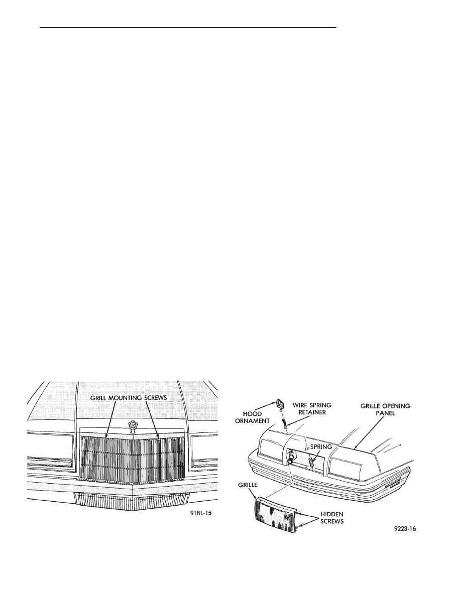
GRILLE AY/P BODY
REMOVAL (FIG. 1)
(1) Remove screws holding grille to opening panel.
(2) Push top of grille downward and pull forward.
(3) Separate grille from vehicle.
INSTALLATION
Reverse the preceding operation.
GRILLE AY/S BODY
REMOVAL (FIG. 2)
(1) Loosen hidden screws holding grille to grille
opening panel at corners of grille. The screws are
captured in a clearance hole covered by a bracket be-
hind the grille.
(2) Pull grille forward from grille opening panel.
INSTALLATION
Reverse the preceding operation.
Fig. 1 Grille—AY/P Body
Fig. 2 Grille—AY/S Body
Ä
AY-BODY
23 - 133