Chrysler Le Baron, Dodge Dynasty, Plymouth Acclaim. Manual - part 120


  Index      Chrysler     Chrysler Le Baron, Dodge Dynasty, Plymouth Acclaim - service repair manual 1993 year


Search            


Content   ..  118  119  120  121   ..


Chrysler Le Baron, Dodge Dynasty, Plymouth Acclaim. Manual - part 120


41TE FOUR SPEED AUTOMATIC TRANSAXLE

INDEX

page

page

41TE Transaxle General Diagnosis

. . . . . . . . . . . 88

Aluminum Thread Repair

. . . . . . . . . . . . . . . . . . . 98

Bearing Adjustment Procedure

. . . . . . . . . . . . . . 141

Clutch Air Pressure Tests

. . . . . . . . . . . . . . . . . . 95

Coolers and Tubes Reverse Flushing

. . . . . . . . . 98

Diagnosis Chart ‘‘B’’ . . . . . . . . . . . . . . . . . . . . . . . 90
Diagnosis Trouble Code Chart ‘‘A’’ . . . . . . . . . . . . 89
Differential Repair

. . . . . . . . . . . . . . . . . . . . . . . 136

Fluid and Filter Changes

. . . . . . . . . . . . . . . . . . . 93

Fluid Drain and Refill

. . . . . . . . . . . . . . . . . . . . . 93

Fluid Leakage-Torque Converter Housing Area

. . 97

Fluid Level and Condition

. . . . . . . . . . . . . . . . . . 93

Gearshift Linkage Adjustment

. . . . . . . . . . . . . . . 98

General Information

. . . . . . . . . . . . . . . . . . . . . . . 85

Hydraulic Pressure Tests

. . . . . . . . . . . . . . . . . . . 94

Input Clutches-Recondition

. . . . . . . . . . . . . . . . 121

Oil Cooler Flow Check

. . . . . . . . . . . . . . . . . . . . 99

Oil Pump Seal Replace

. . . . . . . . . . . . . . . . . . . 136

Park/Neutral Position Switch

. . . . . . . . . . . . . . . 102

Pinion Factor Procedure

. . . . . . . . . . . . . . . . . . 104

Road Test

. . . . . . . . . . . . . . . . . . . . . . . . . . . . . . 93

Selection of Lubricant

. . . . . . . . . . . . . . . . . . . . . 93

Solenoid Assembly-Replace

. . . . . . . . . . . . . . . . 101

Special Additives

. . . . . . . . . . . . . . . . . . . . . . . . . 93

Speed Sensor-Input

. . . . . . . . . . . . . . . . . . . . . . 102

Speed Sensor-Output

. . . . . . . . . . . . . . . . . . . . 103

Torque Converter Clutch Break-In Procedure

. . . 104

Transaxle Quick Learn Procedure

. . . . . . . . . . . 103

Transaxle Recondition

. . . . . . . . . . . . . . . . . . . . 105

Transaxle Removal and Installation

. . . . . . . . . . . 99

Transmission Control Module

. . . . . . . . . . . . . . . 103

Transmission Range Switch

. . . . . . . . . . . . . . . . 102

Valve Body-Recondition

. . . . . . . . . . . . . . . . . . . 132

GENERAL INFORMATION

The 41TE four-speed FWD transaxle uses fully-

adaptive controls. Adaptive controls are those which
perform their functions based on real-time feedback
sensor information. The transaxle uses hydraulically
applied clutches to shift a planetary gear train.

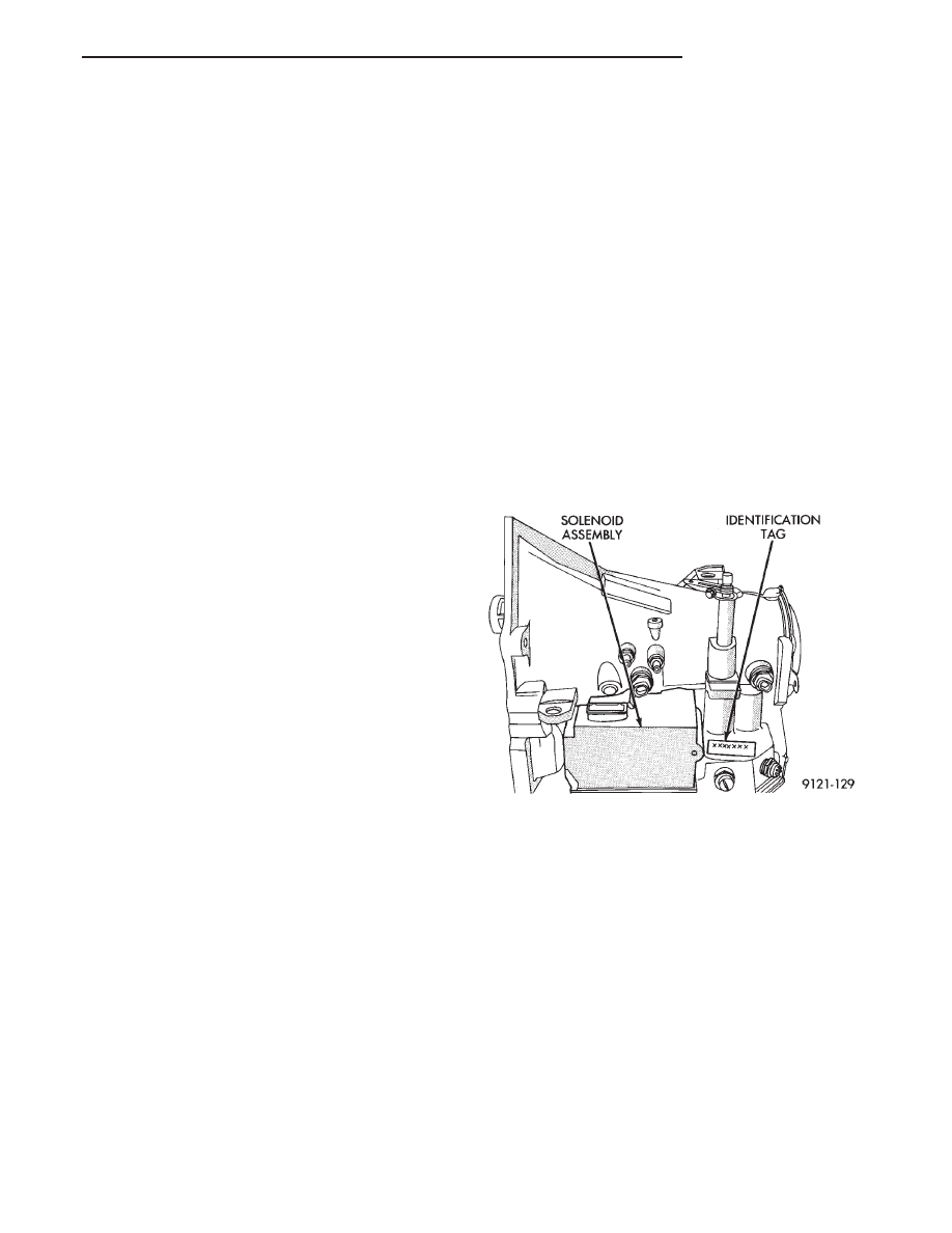
TRANSAXLE IDENTIFICATION

The 41TE transaxle identification code is printed

on a label. The label is located on the transaxle case
next to the solenoid assembly (Fig. 1).

Refer to Figure 2 for an internal view of the tran-

saxle assembly.

Fig. 1 Identification Tag Location

Ä

TRANSAXLE

21 - 85

Fig.

2

Internal

V

iew

of

T

ransaxle

21 - 86

TRANSAXLE

Ä

OPERATION

The 41TE transaxle provides forward ratios of 2.84,

1.57, 1.00, and 0.69 with torque converter clutch
available in 2nd, direct, or overdrive gear; the Re-
verse ratio is 2.21. The shift lever is conventional
with six positions: P, R, N, OD, 3, and L. When OD
is selected the transaxle shifts normally through all
four speeds with torque converter clutch available in
overdrive; this position is recommended for most
driving. The 3 position is tailored for use in hilly or
mountainous driving. When 3 is selected, the trans-
mission uses only 1st, 2nd, and direct gears with
2nd-direct shift delayed to 40 mph or greater. When
operating in 3 or L positions torque converter clutch
application occurs in direct gear for improved trans-
mission cooling under heavy loads. If high engine
coolant temperature occurs, the torque converter
clutch will also engage in 2nd gear. The L position
provides maximum engine braking for descending
steep grades. Unlike most current transaxles, up-
shifts are provided to 2nd or direct gear at peak en-
gine speeds if the accelerator is depressed. This
provides engine over-speed protection and maximum
performance.

CLUTCH AND GEAR

The transaxle consists of:

• Three multiple disc input clutches

• Two multiple disc grounded clutches

• Four hydraulic accumulators

• Two planetary gear sets

This provides four forward ratios and a reverse ra-

tio. The clutch-apply pistons were designed with cen-
trifugally balanced oil cavities so that quick response
and good control can be achieved at any speed. A
push/pull piston is incorporated for two of the three
input clutches.

CAUTION: Some clutch packs appear similar, but
they are not the same. Do not interchange clutch
components as they might fail.

HYDRAULICS

The hydraulics of the transaxle provide the manual

shift lever select function, main line pressure regula-
tion, and torque converter and cooler flow control.
Oil flow to the friction elements is controlled directly
by four solenoid valves. The hydraulics also include a
unique logic-controlled ‘‘solenoid torque converter
clutch control valve’’. This valve locks out the 1st
gear reaction element with the application of 2nd, di-
rect, or overdrive gear elements. It also redirects the
1st gear solenoid output so that it can control torque
converter clutch operation. To regain access to 1st
gear, a special sequence of solenoid commands must
be used to unlock and move the solenoid torque con-
verter clutch control valve. This precludes any appli-

cation of the 1st gear reaction element with other
elements applied. It also allows one solenoid to con-
trol two friction elements.

Small, high-rate accumulators are provided in each

controlled friction element circuit. These serve to ab-
sorb the pressure responses, and allow the controls to
read and respond to changes that are occurring.

SOLENOIDS

Since the solenoid valves perform virtually all con-

trol functions, these valves must be extremely dura-
ble and tolerant of normal dirt particles. For that
reason hardened-steel poppet and ball valves are
used. These are free from any close operating clear-
ances, and the solenoids operate the valves directly
without any intermediate element. Direct operation
means that these units must have very high output
so that they can close against the sizeable flow areas
and high line pressures. Fast response is also re-
quired to meet the control requirements.

Two of the solenoids are normally-venting and two

are normally-applying; this was done to provide a de-
fault mode of operation. With no electrical power, the
transmission provides 2nd gear in OD, 3, or shift
lever positions. All other transmission lever positions
will operate normally. The choice of 2nd gear was
made to provide adequate breakaway performance
while still accommodating highway speeds.

SENSORS

There are three pressure switches to identify sole-

noid application and two speed sensors to read input
(torque converter turbine) and output (parking sprag)
speeds. There is also a position switch to indicate the
manual shift lever position. The pressure switches
are incorporated in an assembly with the solenoids.
Engine speed, throttle position, temperature, etc., are
also observed. Some of these signals are read directly
from the engine control sensors; others are read from
a multiplex circuit with the powertrain control mod-
ule.

ELECTRONICS

The 41TE transmission control module is located

underhood in a potted, die-cast aluminum housing
with a sealed, 60-way connector.

ELECTRONIC MODULATED CONVERTER
CLUTCH (EMCC)

The EMCC enables the torque converter clutch to

partially engage between 23 to 47 MPH before full
engagement at about 50 MPH and beyond. This fea-
ture is on all vehicles equipped with the 41TE tran-
saxle.

ADAPTIVE CONTROLS

These controls function by reading the input and

output speeds over 140 times a second and respond-

Ä

TRANSAXLE

21 - 87

ing to each new reading. This provides the precise
and sophisticated friction element control needed to
make smooth clutch-to-clutch shifts for all gear
changes. The use of overrunning clutches or other
shift quality aids are not required. As with most au-
tomatic transaxles, all shifts involve releasing one el-
ement and applying a different element. In simplified
terms, the upshift logic allows the releasing element
to slip back wards slightly to ensure that it does not
have excess capacity; the apply element is filled until
it begins to make the speed change to the higher
gear; its apply pressure is then controlled to main-
tain the desired rate of speed change until the shift
is complete. The key to providing excellent shift
quality is precision; for example, as mentioned, the
release element for upshifts is allowed to slip back-
wards slightly; the amount of that slip is typically
less than a total of 20 degrees. To achieve that pre-
cision, the transmission control module learns the
characteristics of the particular transaxle that it is
controlling. It learns the release rate of the releasing
element and the apply time of the applying element.
It also learns the rate at which the apply element
builds pressure sufficient to begin making the speed
change. This method achieves more precision than
would be possible with exacting tolerances. It can
also adapt to any changes that occur with age or en-
vironment, for example, altitude, temperature, en-
gine output, etc.

For kickdown shifts, the control logic allows the re-

leasing element to slip and then controls the rate at
which the input (and engine) accelerate; when the
lower gear speed is achieved, the releasing element
reapplies to maintain that speed until the apply ele-
ment is filled. This provides quick response since the
engine begins to accelerate immediately and a
smooth torque exchange since the release element
can control the rate of torque increase. This control
can make any powertrain feel more responsive with-
out in creasing harshness.

Adaptive controls respond to input speed changes.

They compensate for changes in engine or friction el-
ement torque and provide good, consistent shift qual-
ity for the life of the transaxle.

ON-BOARD DIAGNOSTICS

These controls provide comprehensive, on-board

transaxle diagnostics. The information available can
aid in transaxle diagnosis. For example, apply ele-
ment buildup rate indicates solenoid performance.
Also included are self diagnostic functions. Self diag-
nostics allow the technician to test the condition of
the electronic controls. The transmission control
module continuously monitors its critical functions.
It also records any malfunctions, and the number of
engine starts since the last malfunction. This allows
the technician to use the information in the event of
a customer complaint.

41TE TRANSAXLE GENERAL DIAGNOSIS

CAUTION: Before attempting any repair on a 41TE
four speed automatic transaxle, check for diagnos-
tic trouble codes with the DRB II scan tool. Always
use the Powertrain Diagnostic Test Procedure Man-
ual.

Transaxle malfunctions may be caused by these

general conditions:
• Poor engine performance

• Improper adjustments

• Hydraulic malfunctions

• Mechanical malfunctions

• Electronic malfunctions

Diagnosis of these problems should always begin

by checking the easily accessible variables: fluid
level and condition, gearshift cable adjustment. Then
perform a road test to determine if the problem has
been corrected or that more diagnosis is necessary. If
the problem exists after the preliminary tests and
corrections are completed, hydraulic pressure checks
should be performed.

21 - 88

TRANSAXLE

Ä


Content   ..  118  119  120  121   ..