Chrysler Le Baron, Dodge Dynasty, Plymouth Acclaim. Manual - part 109


  Index      Chrysler     Chrysler Le Baron, Dodge Dynasty, Plymouth Acclaim - service repair manual 1993 year


Search            


Content   ..  107  108  109  110   ..


Chrysler Le Baron, Dodge Dynasty, Plymouth Acclaim. Manual - part 109


If vehicle operates properly at highway speeds, but

has poor acceleration, the torque converter stator
overrunning clutch may be slipping. If through-gear
acceleration is normal, but high throttle opening is
required to maintain highway speeds, the torque con-
verter stator clutch may have seized. Both of these
stator defects require replacement of the torque con-
verter.

Observe closely for slipping or engine speed flare-

up. Slipping or flare-up in any gear usually indicates
clutch, band, or overrunning clutch problems. If the
condition is far advanced, an overhaul will probably
be necessary to restore normal operation.

The clutch or band that is slipping can be deter-

mined by noting the transaxle operation in all selec-
tor positions. Then comparing which internal units
are applied in those positions. The Elements in Use
Chart 
provides a basis for road test analysis.

The rear clutch is applied in both the first gear

and first gear positions. Also the overrunning
clutch is applied in first gear and the low/reverse
band is applied in first gear position. If the tran-
saxle slips in range first gear, but does not slip in
first gear, the overrunning clutch is slipping. Sim-
ilarly, if the transaxle slips in any two forward
gears, the rear clutch is slipping.

Using the same procedure, the rear clutch and

front clutch are applied in third gear. If the tran-
saxle slips in third gear, either the front clutch or
the rear clutch is slipping. By selecting another gear
which does not use one of those units, the unit which
is slipping can be determined. If the transaxle also
slips in reverse, the front clutch is slipping. If the
transaxle does not slip in reverse, the rear clutch is
slipping.

The process of elimination can be used to detect

any unit which slips and to confirm proper operation
of good units. Road test analysis can usually diag-
nose slipping units, but the actual cause of the mal-
function usually cannot be decided. Practically any
condition can be caused by leaking hydraulic circuits
or sticking valves.

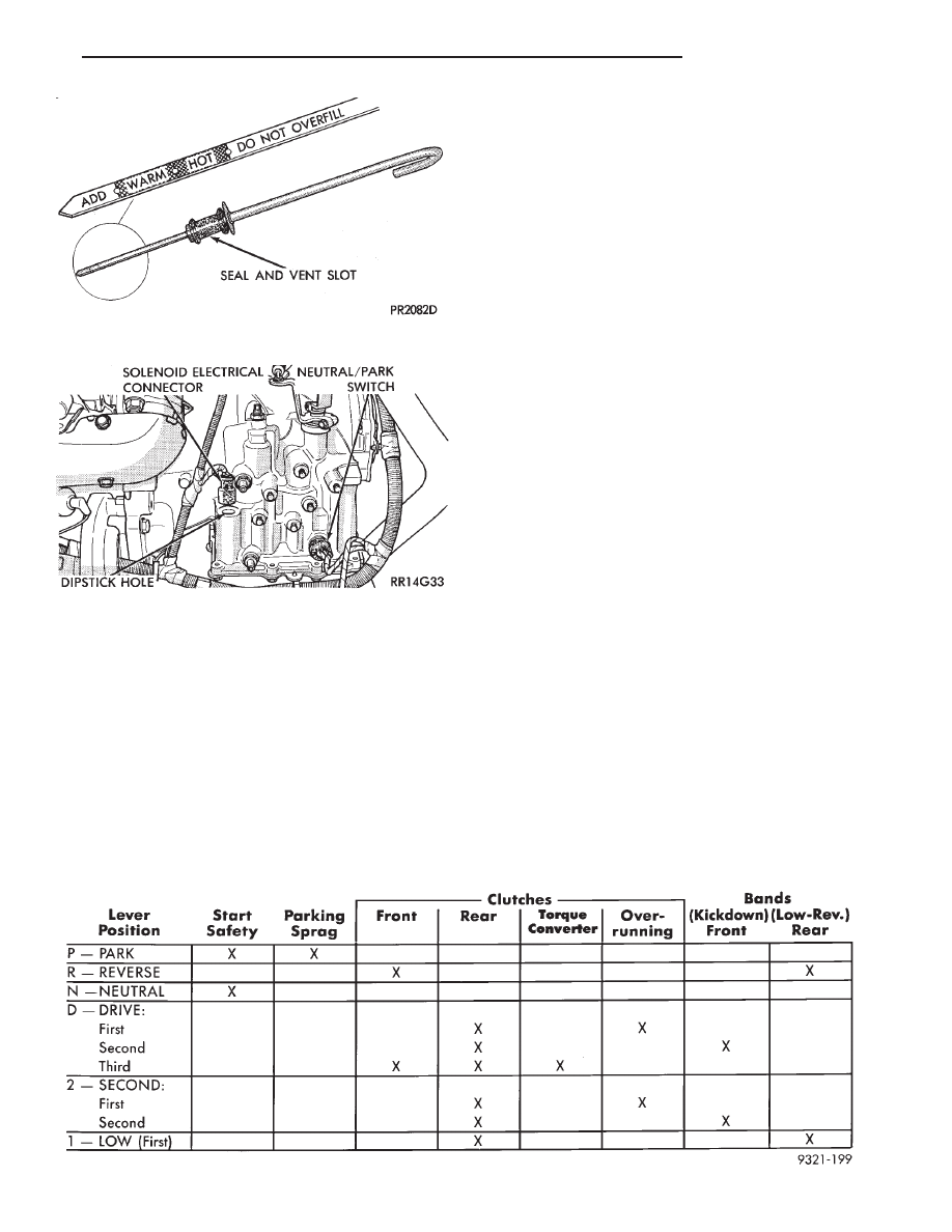
ELEMENTS IN USE AT EACH POSITION OF THE SELECTOR LEVER

Fig. 1 Dipstick and Transaxle Vent

Fig. 2 Torque Converter Clutch Solenoid Wiring

Connector

Ä

TRANSAXLE

21 - 41

Unless the condition is obvious, like no drive in D

range first gear only. The transaxle should never be
disassembled until hydraulic pressure tests have
been performed.

HYDRAULIC PRESSURE TESTS

Pressure testing is a very important step in the di-

agnostic procedure. These tests usually reveal the
cause of most transaxle problems.

Before performing pressure tests, be certain that

fluid level and condition, and control cable adjust-
ments have been checked and approved.

Fluid must be at operating temperature (150 to 200

degrees F.).

Install an engine tachometer, raise vehicle on hoist

which allows front wheels to turn, and position ta-
chometer so it can be read.

Disconnect throttle cable and shift cable from tran-

saxle levers so they can be controlled from outside
the vehicle.

Attach 150 psi gauges to ports required for test be-

ing conducted. A 300 psi gauge (C-3293) is required
for reverse pressure test at rear servo.

Test port locations are shown in (Fig. 3).

TEST ONE (SELECTOR IN 1)

(1) Attach gauges to line and low-reverse ports

(Fig. 3).

(2) Operate engine at 1000 rpm for test.
(3) Move selector lever on transaxle all the way

rearward (position).

(4) Read pressures on both gauges as throttle lever

on transaxle is moved from full clockwise position to
full counterclockwise position.

(5) Line pressure should read 52 to 58 psi with

throttle lever clockwise and gradually increase, as le-
ver is moved counterclockwise, to 80 to 88 psi.

(6) Low-reverse pressure should read the same as

line pressure within 3 psi.

(7) This tests pump output, pressure regulation,

and condition of rear clutch and rear servo hydraulic
circuits.

TEST TWO (SELECTOR IN 2)

(1) Attach one gauge to line pressure port and

tee another gauge into lower cooler line fitting. This
will allow you to read lubrication pressure (Fig 3).

(2) Operate engine at 1000 rpm for test.

Fig. 3 Transaxle (Left Side)

21 - 42

TRANSAXLE

Ä

(3) Move selector lever on transaxle one detent

forward from full rearward position. This is selector
position.

(4) Read pressures on both gauges as throttle lever

on transaxle is moved from full clockwise position to
full counterclockwise position.

(5) Line pressure should read 52 to 58 psi with

throttle lever clockwise and gradually increase, as le-
ver is moved counterclockwise, to 80 to 88 psi.

(6) Lubrication pressure should be 10 to 25 psi

with lever clockwise and 10 to 35 psi with lever full
counterclockwise.

(7) This tests pump output, pressure regulation,

and condition of rear clutch and lubrication hydrau-
lic circuits.

TEST THREE (SELECTOR IN D)

(1) Attach gauges to line and kickdown release

ports (Fig. 3).

(2) Operate engine at 1600 rpm for test.
(3) Move selector lever on transaxle two detents

forward from full rearward position. This is selector
position.

(4) Read pressures on both gauges as throttle lever

on transaxle is moved from full clockwise position to
full counterclockwise position.

(5) Line pressure should read 52 to 58 psi with

throttle lever clockwise and gradually increase, as le-
ver is moved counterclockwise to 80 to 88 psi.

(6) Kickdown release is pressurized only in direct

drive and should be same as line pressure within 3
psi, up to kickdown point.

(7) This tests pump output, pressure regulation,

and condition of rear clutch, front clutch, and hy-
draulic circuits.

TEST FOUR (SELECTOR IN REVERSE)

(1) Attach 300 psi gauge to low-reverse port (Fig.

3).

(2) Operate engine at 1600 rpm for test.
(3) Move selector lever on transaxle four detents

forward from full rearward position. This is selector
position.

(4) Low-reverse pressure should read 180 to 220

psi with throttle lever clockwise and gradually in-
crease, as lever is moved counterclockwise to 260 to
300 psi.

(5) This tests pump output, pressure regulation,

and condition of front clutch and rear servo hydraulic
circuits.

(6) Move selector lever on transaxle to position

to check that low-reverse pressure drops to zero.

(7) This tests for leakage into rear servo, due to

case porosity, which can cause reverse band burn
out.

TEST RESULT INDICATIONS

(1) If proper line pressure, minimum to maximum, is

found in any one test, the pump and pressure regulator
are working properly.

(2) Low pressure in D, 1, and 2 but correct pressure

in indicates rear clutch circuit leakage.

(3) Low pressure in D and R but correct pressure in

indicates front clutch circuit leakage.

(4) Low pressure in R and 1 but correct pressure in

indicates rear servo circuit leakage.

(5) Low line pressure in all positions indicates a

defective pump, a clogged filter, or a stuck pressure
regulator valve.

GOVERNOR PRESSURE

Test only if transaxle shifts at wrong vehicle speeds

when throttle cable is correctly adjusted.

(1) Connect a 0-150 psi pressure gauge to governor

pressure take-off point, located at lower right side of
case, below differential cover (Fig. 3).

(2) Operate transaxle in third gear to read pres-

sures. The governor pressure should respond smoothly
to changes in mph and should return to

0 to 3 psi when vehicle is stopped. High pressure at

standstill (above 3 psi) will prevent the transaxle from
downshifting.

THROTTLE PRESSURE

No gauge port is provided for throttle pressure.

Incorrect throttle pressure should only be suspected if
part throttle upshift speeds are either delayed or occur
too early, with a correctly adjusted throttle cable.
Engine runaway on either upshifts or downshifts can
also be an indicator of incorrect (low) throttle pressure
setting, or misadjusted throttle cable.

In no case should throttle pressure be adjusted until

the transaxle throttle cable adjustment has been veri-
fied to be correct.

CLUTCH AND SERVO AIR PRESSURE TESTS

no drive condition might exist even with correct

fluid pressure, because of inoperative clutches or
bands. The inoperative units, clutches, bands, and
servos can be located through a series of tests by
substituting air pressure for fluid pressure (Fig. 4).

The front and rear clutches, kickdown servo, and

low-reverse servo may be tested by applying air pres-
sure to their respective passages after

the valve body assembly has been removed. To make

air pressure tests, proceed as follows:

Compressed air supply must be free of all dirt

or moisture. Use a pressure of 30 psi.

Remove oil pan and valve body See Disassembly-

Subassembly Removal.

FRONT CLUTCH

Apply air pressure to front clutch apply passage and

listen for a dull thud which indicates that front

Ä

TRANSAXLE

21 - 43

clutch is operating. Hold air pressure on for a few
seconds and inspect system for excessive oil leaks.

REAR CLUTCH

Apply air pressure to rear clutch apply passage

and listen for a dull thud which indicates that rear
clutch is operating. Also inspect for excessive oil
leaks. If a dull thud cannot be heard in the clutches,
place finger tips on clutch housing and again apply
air pressure. Movement of piston can be felt as the
clutch is applied.

KICKDOWN SERVO (FRONT)

Direct air pressure into kickdown servo ON pas-

sage. Operation of servo is indicated by a tightening
of front band. Spring tension on servo piston should
release the band.

LOW AND REVERSE SERVO (REAR)

Direct air pressure into LOW-REVERSE SERVO

APPLY passage. Operation of servo is indicated by a
tightening of rear band. Spring tension on servo pis-
ton should release the band.

If clutches and servos operate properly, no upshift

or erratic shift conditions indicate that malfunctions
exist in the valve body.

FLUID LEAKAGE-TRANSAXLE TORQUE
CONVERTER HOUSING AREA

(1) Check for Source of Leakage.
Since fluid leakage at or around the torque con-

verter area may originate from an engine oil leak,
the area should be examined closely. Factory fill
fluid is dyed red and, therefore, can be distinguished
from engine oil.

(2) Prior to removing the transaxle, perform the

following checks:
• When leakage is determined to originate from the
transaxle, check fluid level prior to removal of the
transaxle and torque converter.
• High oil level can result in oil leakage out the
vent in the dipstick. If the fluid level is high, adjust
to proper level.

After performing this operation, inspect for leak-

age. If a leak persists, perform the following opera-
tion on the vehicle to determine if it is the torque
converter or transaxle that is leaking.

LEAKAGE TEST PROBE

(1) Remove torque converter housing dust shield.
(2) Clean the inside of torque converter housing

(lower area) as dry as possible. A solvent spray fol-
lowed by compressed air drying is preferable.

Fig. 4 Air Pressure Tests

21 - 44

TRANSAXLE

Ä


Content   ..  107  108  109  110   ..