Chrysler Le Baron, Dodge Dynasty, Plymouth Acclaim. Manual - part 107


  Index      Chrysler     Chrysler Le Baron, Dodge Dynasty, Plymouth Acclaim - service repair manual 1993 year


Search            


Content   ..  105  106  107  108   ..


Chrysler Le Baron, Dodge Dynasty, Plymouth Acclaim. Manual - part 107


(8) Verify that a preload condition does not exist.

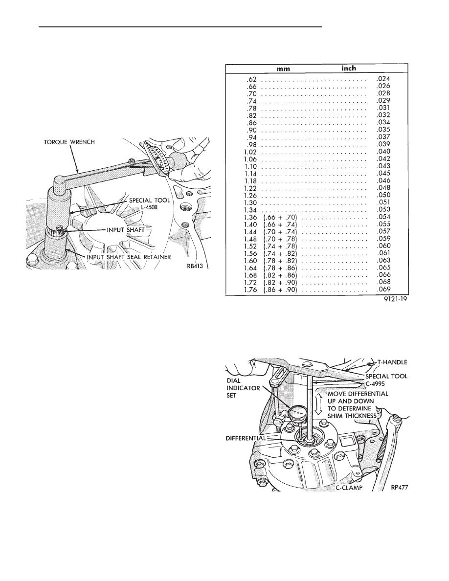
Use Special Tool L-4508 and an inch-pound torque
wrench to check input shaft turning torque (Fig. 2).
The turning torque should be less than 5 in. lbs.

CAUTION: Step (1) MUST be repeated every time a
thinner shim is installed. This will assure that the
input shaft bearing cup is pressed the proper dis-
tance into the case. If the turning torque is too high,
install a .04mm (.0016 inch) thinner shim.

(9) Recheck input shaft turning torque. Repeat step

(8) until the proper bearing turning torque is obtained.
Observe CAUTION in step (8).

DIFFERENTIAL BEARING PRELOAD ADJUSTMENT

(1) Remove bearing cup and existing shim from

differential bearing retainer. (See Differential Bearing
Retainer in Subassembly Recondition section).

(2) Select a gauging shim which will give 0.025 to

0.254mm (.001 to .010 inch) end play. SUGGESTION:
Measure original shim from differential bearing
retainer and select a shim 0.381mm (.015 inch-
)thinner than original for the gauging shim. 
In-
stall gauging shim in differential bearing retainer and
press in bearing cup. Installation of oil baffle is not
necessary when checking differential assembly
end play.

(3) Oil differential bearings with SAE 5W-30 engine

oil and install differential assembly in transaxle case.
Check extension housing O-ring for damage (replace if
necessary). Add a 1/16 inch bead of MOPAR

t Gasket

Maker, Loctite 518, or equivalent to extension flange.
Install extension housing and differential bearing re-
tainer. Torque bolts (see Tightening Reference).

(4) Position transaxle with bell housing facing down

on workbench with C-clamps. Position dial indicator.

(5) Apply a medium load to differential with Tool

C-4995 and a T-Handle, in the downward direction.

Roll differential assembly back and forth a number of
times. This will settle the bearings. Zero dial indicator.
To obtain end play readings, apply a medium load in
the upward direction while rolling differential assem-
bly back and forth (Fig. 3). Record end play.

(6) The shim required for proper bearing preload is

total of gauging shim thickness, plus end play,

Fig. 2 Checking Input Shaft Bearing Turning Torque

INPUT SHAFT SHIM CHART

Fig. 3 Checking Differential Bearing End Play to De-

termine Shim Thickness

Ä

TRANSAXLE

21 - 33

plus (constant) preload of 0.254mm (.010 in.).
Combine shims, if necessary, to obtain a shim within
.05mm (.002 inch) of the required shim (see Shim
Chart for proper shims).

(7) Remove differential bearing retainer. Remove

bearing cup and gauging shim. Properly install oil
baffle. Be sure oil baffle is not damaged. Install
shim(s) selected in step (6). Then press in the bearing
cup into differential bearing retainer.

(8) Using a 1/16 inch bead of MOPAR

t Gasket

Maker, Loctite 518, or equivalent for gasket, install
differential bearing retainer. Torque all bolts (See
Tightening Reference).

(9) Using Special Tool C-4995 and an inch-pound

torque wrench, check turning torque of the differential
assembly in clockwise and counterclockwise directions
(Fig. 4). The turning torque should be 9 to 14 in.
lbs. for new bearings or a minimum of 6 in. lbs.
for used bearings. If the turning torque is too
high, install a .05mm (.002 inch) thinner shim. If
the turning torque is too low, install a .05mm
(.002 inch) thicker shim.

(10) Recheck turning torque. Repeat Step (9) until

the proper turning torque is obtained.

Fig. 4 Checking Differential Bearing Turning Torque

DIFFERENTIAL BEARING SHIM CHART

21 - 34

TRANSAXLE

Ä

THREE SPEED TORQUEFLITE AUTOMATIC TRANSAXLE

INDEX

page

page

Accumulator-Recondition

. . . . . . . . . . . . . . . . . . . 67

Aluminum Thread Repair

. . . . . . . . . . . . . . . . . . . 48

Assembly Subassembly Installation

. . . . . . . . . . . 57

Band Adjustment

. . . . . . . . . . . . . . . . . . . . . . . . . 47

Bearing Adjustment Procedures

. . . . . . . . . . . . . . 81

Clutch and Servo Air Pressure Tests

. . . . . . . . . . 43

Differential Repair

. . . . . . . . . . . . . . . . . . . . . . . . 76

Disassembly Subassembly Removal

. . . . . . . . . . 50

Fluid and Filter Change

. . . . . . . . . . . . . . . . . . . . 40

Fluid Drain and Refill

. . . . . . . . . . . . . . . . . . . . . 40

Fluid Leakage-Transaxle Torque Converter

Housing Area

. . . . . . . . . . . . . . . . . . . . . . . . . . 44

Fluid Level and Condition

. . . . . . . . . . . . . . . . . . 40

Front Clutch-Recondition

. . . . . . . . . . . . . . . . . . . 62

Front Planetary & Annulus Gear-Recondition

. . . . 65

Gearshift Linkage Adjustment

. . . . . . . . . . . . . . . 46

General Information

. . . . . . . . . . . . . . . . . . . . . . . 35

Governor

. . . . . . . . . . . . . . . . . . . . . . . . . . . . . . . 48

Hydraulic Control Pressure Adjustments

. . . . . . . 47

Hydraulic Pressure Tests

. . . . . . . . . . . . . . . . . . . 42

Kickdown Servo (Controlled Load)-Recondition

. . 67

Low/Reverse Servo-Recondition

. . . . . . . . . . . . . . 66

Oil Cooler Flow Check

. . . . . . . . . . . . . . . . . . . . 48

Oil Coolers and Tubes Reverse Flushing

. . . . . . 48

Oil Pump-Recondition

. . . . . . . . . . . . . . . . . . . . . 62

Output Shaft Repair

. . . . . . . . . . . . . . . . . . . . . . 71

Park/Neutral Position and Back-Up Lamp Switch

. 47

Parking Pawl

. . . . . . . . . . . . . . . . . . . . . . . . . . . . 71

Pump Oil Seal-Replacement

. . . . . . . . . . . . . . . . 61

Rear Clutch-Recondition

. . . . . . . . . . . . . . . . . . . 64

Road Test

. . . . . . . . . . . . . . . . . . . . . . . . . . . . . . 40

Selection of Lubricant

. . . . . . . . . . . . . . . . . . . . . 40

Special Additives

. . . . . . . . . . . . . . . . . . . . . . . . . 40

Three Speed Torqueflite General Diagnosis

. . . . . 36

Throttle Pressure Linkage Adjustment

. . . . . . . . . 46

Torque Converter Clutch Solenoid Wiring

Connector

. . . . . . . . . . . . . . . . . . . . . . . . . . . . 40

Transaxle and Torque Converter Removal

. . . . . . 48

Transfer Shaft Repair

. . . . . . . . . . . . . . . . . . . . . 68

Valve Body-Recondition

. . . . . . . . . . . . . . . . . . . . 57

Vehicle Speed Sensor Pinion Gear

. . . . . . . . . . . 47

GENERAL INFORMATION

Safety goggles should be worn at all times

when working on these transaxles.

This transaxle combines a fully automatic 3 speed

transmission, final drive gearing, and differential into
a front wheel drive system. The unit is a Metric
design. The identification markings and usage of the
transaxle are charted in Diagnosis and Tests.

Transaxle operation requirements are differ-

ent for each vehicle and engine combination and
some internal parts will be different to provide
for this. Therefore, when replacing parts, refer to
the seven digit part number stamped on rear of
the transaxle oil pan flange.

Within this transaxle, there are 3 primary areas:
(1) Main center line plus valve body.
(2) Transfer shaft center line (includes governor and

parking sprag).

(3) Differential center line. Center distances be-

tween the main rotating parts in these 3 areas are held
precise. This maintains a low noise level through
smooth accurate mesh of the gears.

The torque converter, transaxle area, and differential

are housed in an integral aluminum die casting. The
differential oil sump is common with the transaxle
sump. 
Separate filling of the differential is NOT nec-
essary.

The torque converter is attached to the crankshaft

through a flexible driving plate. Cooling of the con-
verter is accomplished by circulating the transaxle
fluid through an oil-to-water type cooler located in the
radiator side tank and/or an oil-to air heat ex-

changer. The torque converter assembly is a sealed
unit that cannot be disassembled.

The transaxle fluid is filtered by an internal filter

attached to the lower side of the valve body assem-
bly.

Engine torque is transmitted to the torque con-

verter then, through the input shaft to multiple-disc
clutches in the transaxle. The power flow depends on
the application of the clutches and bands. Refer to
Elements in Use Chart in Diagnosis and Tests sec-
tion. The transaxle consists of two multiple-disc
clutches, an overrunning clutch, two servos, a hy-
draulic accumulator, two bands, and two planetary
gear sets. They provide three forward ratios and a re-
verse ratio. The common sun gear of the planetary
gear sets is connected to the front clutch by a driving
shell. The drive shell is splined to the sun gear and
to the front clutch retainer. The hydraulic system
consists of an oil pump, and a single valve body
which contains all of the valves except the governor
valves. The transaxle sump and differential sump are
both vented through the dipstick. Output torque
from the main center line is delivered through heli-
cal gears to the transfer shaft. This gear set is a
factor of the final drive (axle) ratio. The shaft also
carries the governor and parking sprag. An integral
helical gear on the transfer shaft drives the differen-
tial ring gear. The final drive gearing is completed
with one of three gear sets producing overall top gear
ratios of 2.78, 3.02, or 3.22 depending on model and
application.

Ä

TRANSAXLE

21 - 35

TORQUE CONVERTER CLUTCH

The torque converter clutch is standard on all ve-

hicles. It is activated only in direct drive and is con-
trolled by the engine electronics. A solenoid on the
valve body, is powered by the powertrain control mod-
ule to activate torque converter clutch.

HYDRAULIC CONTROL SYSTEM

The hydraulic control circuits show the position of

the various valves. They indicate those under hydrau-
lic pressure for all operations of the transaxle.

The hydraulic control system makes the transaxle

fully automatic, and has four important functions to
perform. In a general way, the components of any
automatic control system may be grouped into the
following basic groups:

The pressure supply system, the pressure regulating

valves, the flow control valves, the clutches, and band
servos.

Taking each of these basic groups or systems in turn,

the control system may be described as follows:

PRESSURE SUPPLY SYSTEM

The pressure supply system consists of an oil pump

driven by the engine through the torque converter. The
single pump furnishes pressure for all the hydraulic
and lubrication requirements. Oil pump housing
assemblies are available with preselected pump
gears.

PRESSURE REGULATING VALVES

The pressure regulating valve controls line pressure

dependent on throttle opening. The governor valve
transmits regulated pressure to the valve body (in
conjunction with vehicle speed) to control upshift and
downshift.

The throttle valve transmits regulated pressure to

the transaxle (dependent on throttle position) to con-
trol upshift and downshift.

FLOW CONTROL VALVES

The manual valve provides the different transaxle

drive ranges as selected by the vehicle operator.

The 1-2 shift valve automatically shifts the transaxle

from first to second or from second to first, depending
on the vehicle operation.

The 2-3 shift valve automatically shifts the transaxle

from second to third or from third to second depending
on the vehicle operation.

The kickdown valve makes possible a forced down-

shift from third to second, second to first, or third to
first (depending on vehicle speed). This can be done by
depressing the accelerator pedal past the detent ‘‘feel’’
near wide open throttle.

The shuttle valve has two separate functions and

performs each independently of the other. The first
provides fast release of the kickdown band, and
smooth front clutch engagement, when the driver

makes a lift-foot upshift from second to third. The
second function of the shuttle valve is to regulate the
application of the kickdown servo and band when
making third to second kickdown.

The by-pass valve provides for smooth application of

the kickdown band on 1-2 upshifts.

The torque converter clutch solenoid allows for the

electronic control of the clutch inside the torque con-
verter. It also disengages the torque converter at closed
throttle, during engine warm-up, and during part-
throttle acceleration.

The switch valve directs oil to apply the torque

converter clutch in one position and releases the torque
converter clutch in the other position.

CLUTCH, BAND SERVO, AND ACCUMULATOR

The front and rear clutch pistons, and both servo

pistons are moved hydraulically to engage the clutches
and apply the bands. The pistons are released by
spring tension when hydraulic pressure is released. On
the 2-3 upshift, the kickdown servo piston is released
by spring tension and hydraulic pressure.

The accumulator controls the hydraulic pressure on

the apply side of the kickdown servo during the 1-2
upshift; thereby, cushioning the kickdown band appli-
cation at any throttle position.

GEARSHIFT AND PARKING LOCK CONTROLS

The transaxle is controlled by a lever type gearshift

incorporated within the console or the steering column.
The control has six selector lever positions: P (park), R
(reverse), N (neutral), and D (drive), 2 (second), and 1
(first). The parking lock is applied by moving the
selector lever past a gate to the position. Do not
apply the parking lock until the vehicle has
stopped; otherwise, a severe banging noise will
occur.

THREE SPEED TORQUEFLITE GENERAL DIAGNO-
SIS

Automatic transaxle malfunctions may be caused by

four general conditions:
• Poor engine performance

• Improper adjustments

• Hydraulic malfunctions

• Mechanical malfunctions.

Diagnosis of these problems should always begin by

checking the easily accessible variables: fluid level and
condition, gearshift cable adjustment, and throttle
pressure cable adjustment. Then perform a road test to
determine if the problem has been corrected or that
more diagnosis is necessary. If the problem exists after
the preliminary tests and corrections are completed,
hydraulic pressure tests should be performed.

21 - 36

TRANSAXLE

Ä


Content   ..  105  106  107  108   ..