Chrysler Le Baron, Dodge Dynasty, Plymouth Acclaim. Manual - part 72


  Index      Chrysler     Chrysler Le Baron, Dodge Dynasty, Plymouth Acclaim - service repair manual 1993 year


Search            


Content   ..  70  71  72  73   ..


Chrysler Le Baron, Dodge Dynasty, Plymouth Acclaim. Manual - part 72


bolts and nut on locating stud (Fig. 2). The right rear
crossmember stud is a pilot that correctly locates
the crossmember. Tighten down this bolt first,
then torque all 4 crossmember fasteners to 122
N

Im (90 ft. lbs.).

CAUTION: Proper torque on the crossmember to
frame rail mounting bolts is very important.

(3) Torque the 4 bolts (Fig. 3) attaching the steering

gear assembly to front crossmember, to 68 N

Im (50 ft.

lbs.). To ensure proper alignment of the steering
gear tighten left front bolt first.

(4) Attach the engine damper strut from the engine

to the crossmember (if so equipped).

(5) Attach the fluid tubes (Fig. 3) from the power

steering pump to the fittings on the steering gear.
Torque the fluid pressure line to steering gear tube nut
to 31 N

Im (275 in. lbs.).

(6) Mount the outer tie rod ends to the steering

knuckles. Install the tie rod end to steering knuckle
attaching nuts. Torque the tie rod end to steering
knuckle nuts to 52 N

Im (38 ft. lbs.). Install cotter pin

in tie rod end.

(7) Install the front tire and wheel assemblies on

vehicle. Install the wheel lug nuts and torque to 129
N

Im (95 ft. lbs.).

(8) Lower vehicle.

CAUTION: Do not use automatic transmission fluid.

(9) Fill power steering pump fluid reservoir to the

(Full-Cold) proper level.

(10) Start the engine and let run for a few seconds.

Then turn the

engine off.
(11) Add fluid if necessary.
(12) Raise front wheels of vehicle off the ground.
(13) Start engine and turn steering wheel several

times from stop to stop to bleed air from fluid in
system. Stop engine, check fluid level, and inspect
system for leaks. Fill pump reservoir to correct
level with Mopar

t, Power Steering Fluid, or

equivalent. See Checking Fluid Level.

(14) Lower front wheels of vehicle back on the

ground.

(15) Adjust toe (Refer to Group 2 Suspension).
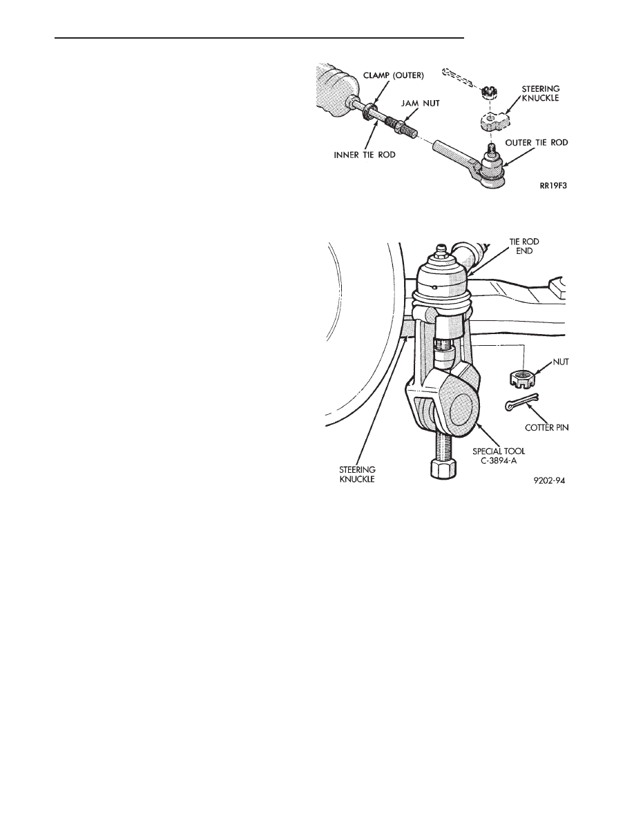
OUTER TIE ROD

REMOVAL

(1) Loosen inner tie rod to outer tie rod jam nut (Fig.

4).

(2) Remove outer tie rod to steering knuckle cotter

pin and attaching nut (Fig. 4).

(4) Remove the tie rod end from steering knuckles,

using Puller Special Tool C-3894-A (Fig. 5).

(5) Remove outer tie rod from inner tie rod.

INSTALLATION

(1) Install outer tie rod onto inner tie rod. Make

sure jam nut is on inner tie rod (Fig. 4).

(2) Do not tighten jam nut.
(3) Install outer tie rod onto steering knuckle. In-

stall tie rod to steering knuckle attaching nut and
torque to 52 N

Im (38 ft.lbs.).

CAUTION: During this procedure do not allow the
steering gear boot to become twisted. 
(See Wheel
Alignment in the suspension section of this service
manual).

(4) Make toe adjustment by turning inner tie rod.
(5) Tighten the inner to outer tie rod jam nut to 75

N

Im (55 ft. lbs.) torque. Lubricate tie rod boot groove

with silicone type lubricant before installing outer
boot clamp, making sure boot is not twisted.

Fig. 4 Outer Tie Rod

Fig. 5 Tie Rod End Removal

Ä

STEERING

19 - 27

ACUSTAR STANDARD AND TILT STEERING COLUMN

INDEX

page

page

General Information

. . . . . . . . . . . . . . . . . . . . . . . 28

Ignition Switch Service

. . . . . . . . . . . . . . . . . . . . 34

Steering Column Component Service

. . . . . . . . . 34

Steering Column Service Procedures

. . . . . . . . . . 30

GENERAL INFORMATION

WARNING: THE AIR BAG SYSTEM IS A SENSITIVE,
COMPLEX ELECTRO-MECHANICAL UNIT. BEFORE
ATTEMPTING TO DIAGNOSE, REMOVE OR IN-
STALL THE AIR BAG SYSTEM COMPONENTS YOU
MUST FIRST DISCONNECT AND ISOLATE THE
BATTERY NEGATIVE (GROUND) CABLE. FAILURE
TO DO SO COULD RESULT IN ACCIDENTAL DE-
PLOYMENT OF THE AIR BAG AND POSSIBLE PER-
SONAL INJURY.

THE FASTENERS, SCREWS, AND BOLTS, ORIGI-

NALLY USED FOR THE AIR BAG COMPONENTS,
HAVE SPECIAL COATINGS AND ARE SPECIFI-

CALLY DESIGNED FOR THE AIR BAG SYSTEM.
THEY MUST NEVER BE REPLACED WITH ANY
SUBSTITUTES. ANYTIME A NEW FASTENER IS
NEEDED, REPLACE WITH THE CORRECT FASTEN-
ERS PROVIDED IN THE SERVICE PACKAGE OR
FASTENERS LISTED IN THE PARTS BOOKS.

BEFORE

SERVICING

A

STEERING

COLUMN

EQUIPPED WITH AN AIR BAG, REFER TO GROUP
8M, ELECTRICAL FOR PROPER AND SAFE SER-
VICE PROCEDURES.

Safety goggles should be worn at all times

when working on steering columns.

19 - 28

STEERING

Ä

Fig.

1

Acustar

Standard

and

T

ilt

Steering

Column

Ä

STEERING

19 - 29

The Acustar tilt and standard column (Fig. 1) has

been designed to be serviced as an assembly; less wir-
ing, switches, shrouds, steering wheel, etc. Also, most
steering column components can be serviced without re-
moving the steering column from the vehicle.

CAUTION: Disconnect negative (ground) cable from
battery, before servicing any column component.

CAUTION: Do not attempt to remove the pivot pins
to disassemble the tilting mechanism. Damage will
occur.

STEERING COLUMN SERVICE PROCEDURES

To service the steering wheel and its components

or the air bag, refer to Group 8M, Restraint Systems.
Follow all WARNINGS.

To service the switches, refer to the appropriate

section of Group 8, Electrical.

To replace the steering column assembly, refer to the

steering column removal procedure. For location of com-
ponents referred to in the procedure see (Fig. 1).

WARNING: BEFORE BEGINNING ANY AIR BAG
SYSTEM

COMPONENT

INSTALLATION

OR

RE-

MOVAL PROCEDURES. REMOVE AND ISOLATE
THE NEGATIVE (-) BATTERY CABLE (GROUND)
FROM THE VEHICLE BATTERY. THIS IS THE ONLY
SURE WAY TO DISABLE THE AIR BAG SYSTEM.
FAILURE TO DO THIS COULD RESULT IN ACCI-
DENTAL AIR BAG DEPLOYMENT AND POSSIBLE
PERSONAL INJURY.

STEERING COLUMN REMOVAL

(1) Make sure the front wheels of the vehicle are

in the straight ahead position.

(2) Disconnect the negative (ground) cable from

the battery and isolate cable.

(3) For vehicles equipped with a column shift. Dis-

connect the transmission shift cable from the steer-
ing column by prying it out of the grommet in the
shift lever (Fig. 2).

(4) Remove the steering wheel center pad. Discon-

nect electrical components such as horn lead, air bag
lead and speed control switch lead (if equipped) from
center pad (Fig. 3).

(5) Remove the steering wheel retaining nut from

the steering column shaft. Remove steering wheel
from shaft using Puller, Special Tool C-3428-B (Fig.
4). Do not bump or hammer on steering column
shaft to remove wheel.

(6) Remove the lower steering column cover (Fig.

5).

(7) Remove the retaining pin in the upper to lower

steering coupler retaining bolt (Fig. 6).

Fig. 2 Shift Cable Removal From Grommet

Fig. 3 Horn Pad Removal (Typical)

Fig. 4 Removing Steering Wheel (Typical)

19 - 30

STEERING

Ä


Content   ..  70  71  72  73   ..