Chrysler Le Baron, Dodge Dynasty, Plymouth Acclaim. Manual - part 70


  Index      Chrysler     Chrysler Le Baron, Dodge Dynasty, Plymouth Acclaim - service repair manual 1993 year


Search            


Content   ..  68  69  70  71   ..


Chrysler Le Baron, Dodge Dynasty, Plymouth Acclaim. Manual - part 70


(18) Lower vehicle.
(19) Install the serpentine drive belt. Refer to (Fig.

10) for correct serpentine belt routing. See Cooling,
Group 7 for detailed installation procedure.

CAUTION: Do not use automatic transmission fluid
in power steering system. Only use Mopar

T

, Power

Steering Fluid, or equivalent.

(20) Fill power steering pump reservoir to correct

fluid level.

(21) Connect the negative battery cable on the

negative battery post.

(22) Start engine and turn steering wheel several

times from stop to stop to bleed air from fluid in sys-
tem. Stop engine, check fluid level, and inspect sys-
tem for leaks. See Checking Fluid Level.

TURBO III

REMOVE

(1) Disconnect the battery (-) negative cable from

the battery and isolate cable.

(2) Raise vehicle See Hoisting, Group 0. Put oil

drain pan under vehicle to catch power steering
fluid.

(3) Remove the right front underhood splash shield

for access to the serpentine belt tensioner.

(4) Release the tension on the serpentine drive belt

tensioner and remove drive belt from power steering
pump pulley (Fig. 20). Drive belt does not have to be
fully removed from engine.

(5) Remove the power steering fluid return hose at

the steering gear metal tube. Let power steering
fluid drain from the hose and power steering pump
into drain pan.

(6) Remove the high pressure fluid line banjo bolt

fitting from the power steering pump. Remove high
pressure power steering fluid line from the power
steering pump.

(7) Remove the lower power steering pump to

bracket mounting nut and fluid hose routing clip. Re-
move the 2 bolts and the stud attaching the power
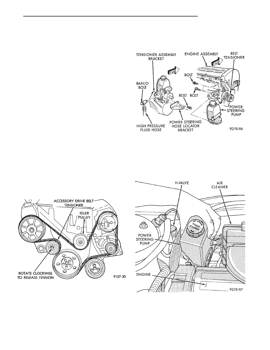
steering pump to its mounting bracket (Fig. 21).

(8) Lower vehicle.
(9) Remove the wiring harness electrical connector

from the H-valve on the air conditioning fluid lines.

(10) Remove the power steering pump from the ve-

hicle out through the area between the cylinder head
and the dash panel (Fig. 22).

(11) Transfer the required components from the

failed power steering pump to the replacement power
steering pump. See the appropriate area of this ser-
vice manual section for the component replacement
procedures.

Fig. 20 Turbo III Accessory Drive Belt Routing

Fig. 21 Power Steering Pump Mounting

Fig. 22 Power Steering Pump Removal From Vehicle

Ä

STEERING

19 - 19

INSTALL

(1) Install the power steering pump back into the

vehicle in the reverse order of removal, between cyl-
inder head and dash panel (Fig. 20).

(2) Install the wiring harness connector back on

the H-valve located on the air conditioning fluid
lines (Fig. 20).

(3) Raise vehicle See Hoisting, Group 0.
(4) Install the power steering pump on its mount-

ing bracket, and the hose locator bracket. Install the
bolt/stud and 2 bolts attaching the power steering
pump to its mounting bracket, and the bolts attach-
ing the hose locator bracket (Fig. 19). Torque all fas-
teners to 31 N

Im (280 in. lbs.).

(5) Install the power steering fluid pressure hose,

banjo bolt and seal washer onto power steering pump
(Fig. 4). Pressure hose is to be installed so it is
routed to the left of the hose locator bracket (Fig.
19). Torque the banjo bolt to 31 N

Im (275 in. lbs.).

Inspect the O-rings on the banjo bolt to ensure
they are not damaged and located correctly.

(6) Install the low pressure fluid return hose from

the power steering pump back on the steel tube on
the steering gear (Fig. 4). Install hose clamp, be sure
the hose clamp is installed past the retaining bead
the steel tube. Install the hose routing clip on the
power steering pump bolt/stud, install clip retaining
nut and tighten.

(7) Install the serpentine accessory drive belt (Fig.

18). Be sure the belt is correctly installed and
aligned on all pulleys before starting engine.

(8) Install the right front underhood splash shield.

CAUTION: Do not use automatic transmission fluid
in power steering system. Only use Mopar

T

, Power

Steering Fluid, or equivalent.

(9) Fill power steering pump reservoir to correct

fluid level.

(10) Connect the negative battery cable on the

negative battery post.

(11) Start engine and turn steering wheel several

times from stop to stop to bleed air from fluid in sys-
tem. Stop engine, check fluid level, and inspect sys-
tem for leaks. See Checking Fluid Level.

POWER STEERING PUMP PULLEY SERVICE

SAGINAW VANE SUBMERGED PUMP

REMOVE

(1) Remove the pulley with Puller C-4333 (C-4068)

(Fig. 1).

CAUTION: Do not hammer on power steering pump
pulley. This will damage the pulley and the power
steering pump.

(2) Replace pulley if bent, cracked, or loose.

INSTALLATION

(1) Install the pulley with Installer C-4063 (Fig.2).

Do not use the tool adapters.

(2) Ensure that the tool and the pulley remain

aligned with the pump shaft. Prevent the pulley from
being cocked on the shaft.

(3) Force pulley flush with the end of the shaft.

Fig. 1 Pulley Removal (Typical)

Fig. 2 Pulley Installation (Typical)

19 - 20

STEERING

Ä

With Serpentine Belts; Run engine until warm (5

min.) and note any belt chirp. If chirp exists, move
pulley outward approximately 0.5 mm (0.020 in.). If
noise increases, press on 1.0mm (0.040 in.). Be careful
that pulley does not contact mounting bolts.

SAGINAW T/C STYLE PUMP

REMOVE

(1) Mount power steering pump assembly in a vise

using one of the pump mounting bosses (Fig. 3). Do not
clamp the body of the power steering pump in vise.

Do not press or hammer on the shaft of the

power steering pump in an attempt to remove
the pulley. This will damage the internal compo-
nents of the power steering pump.

(2) Remove the power steering pump pulley from the

power steering pump shaft using Puller, Special Tool
C-4333 (Fig. 4).

INSTALL

Do not press or hammer on the shaft of the

power steering pump in an attempt to install the
pulley. This will damage the internal components
of the power steering pump.

(1) Place the power steering pump pulley on the end

of the power steering pump shaft. Make sure the pulley
is installed squarely on the end of the shaft (Fig. 5).

CAUTION: When installing the pulley on the Saginaw
T/C style power steering pump. The spacer that is
provided with either the replacement power steering
pump or pulley MUST be used when the pulley is in-

stalled on the pump. The spacer provides for the cor-
rect pulley location on the power steering pump to
provide correct accessory drive belt alignment. The
alignment is critical in controlling accessory drive belt
noise. It also prevents the pulley from contacting the
power steering pump when it is installed, causing
power steering pump or pulley damage.

(2) Install the spacer provided with the replacement

power steering pump or power steering pulley into the
hub of the power steering pump pulley (Fig. 5).

(3) Insert the Pulley Installer, Special Tool C-4063,

(without adapters) through hole in spacer. Then
thread it into the end of the power steering pump
shaft (Fig. 6). Tighten the installer into shaft.

Fig. 4 Removing Power Steering Pump Pulley

Fig. 5 Pulley And Spacer Installed On Pump

Fig. 3 Power Steering Pump Mounted In Vise

Ä

STEERING

19 - 21

(4) Hold the Pulley Installer with one wrench so it

will not rotate. Turn hex (Fig. 6) down threaded rod
of installer pushing the pulley onto the shaft of the
power steering pump (Fig. 6). Ensure that the tool
and the pulley remain aligned with the pump shaft
so pulley does not become cocked on shaft.

(5) Continue to push pulley onto shaft of power

steering pump until Pulley Installer, Special Tool
C-4063 will no longer turn. This will ensure the
spacer provided is fully seated against the front of
the power steering pump shaft (Fig. 7).

(6) Remove

the

Pulley

Installer,

Special

Tool

C-4063 from the shaft of the power steering pump.
Remove the supplied spacer from the hub of the
power steering pump pulley and discard.

POWER STEERING PUMP FLUID RESERVOIRS

VANE SUBMERGED PUMP (HAM CAN)

REMOVE

Discard all O-ring seals during disassembly,

they are not re-usable.

(1) Remove the filler cap and drain the fluid from

reservoir before removing parts.

(2) Remove mounting studs and pressure fitting

(Fig. 1). Rock reservoir by hand or use a soft face
mallet to remove.

(3) Remove O-ring seals from housing and reser-

voir (Fig.1).

(4) Remove flow control valve and spring from

housing.

INSTALL

Clean all parts before installation. Lubricate

new O-ring seals with Mopar

Power Steering

Fluid or equivalent.

(1) Install flow control valve and spring (Fig. 2).
(2) Install new O-ring seals in housing (Fig.1). In-

stall the pump housing assembly into the fluid reser-
voir. Tighten mounting studs to 48 N

Im (35 ft. lbs.)

torque.

(3) Install fitting in flow control valve bore. Tighten

the fitting to 75 N

Im (55 ft. lbs.) torque.

SAGINAW T/C STYLE PUMP WITH INTEGRAL
RESERVOIR

REMOVAL

Discard all O-ring seals during disassembly,

they are not re-usable.

(1) Remove pump and clean exterior of pump with

solvent.

(2) Remove the filler cap and drain the fluid from

reservoir.

(3) Clamp the front hub of the pump in a soft jaw

vice.

(4) Pry up tab and slide the retaining clip off (Fig. 3).
(5) Remove fluid reservoir from pump body. Remove

and discard O-ring seal (Fig. 4).

INSTALLATION

(1) Lubricate new O-ring Seal with Mopar Power

Steering Fluid or equivalent.

(2) Install seal in housing (Fig. 4).
(3) Install reservoir onto housing (Fig. 4).

Fig. 6 Installing Power Steering Pump Pulley

Fig. 7 Power Steering Pump Pulley Installed

19 - 22

STEERING

Ä


Content   ..  68  69  70  71   ..