Index Chrysler Chrysler Le Baron, Dodge Dynasty, Plymouth Acclaim - service repair manual 1993 year
Search
Content .. 65 66 67 68 ..
Chrysler Le Baron, Dodge Dynasty, Plymouth Acclaim. Manual - part 67
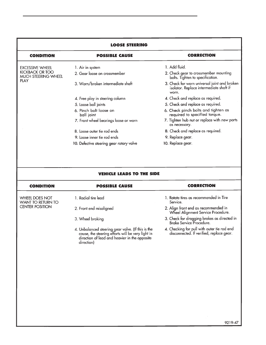
POWER STEERING SERVICE DIAGNOSIS
Ä
STEERING
19 - 7