Chrysler Le Baron, Dodge Dynasty, Plymouth Acclaim. Manual - part 65


  Index      Chrysler     Chrysler Le Baron, Dodge Dynasty, Plymouth Acclaim - service repair manual 1993 year


Search            


Content   ..  63  64  65  66   ..


Chrysler Le Baron, Dodge Dynasty, Plymouth Acclaim. Manual - part 65


is made with the camshaft gear. While holding the
sensor in this position, install and tighten the retain-
ing bolt 12 N

Im (105 in. lbs.) torque.

(2) Connect camshaft position sensor electrical con-

nector to harness connector. Position connector away
from the accessory belt.

HEATED OXYGEN SENSOR (O

2

SENSOR) SERVICE

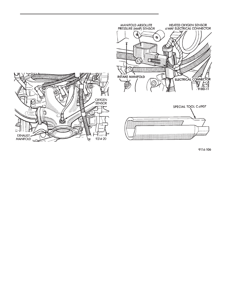
The oxygen sensor is installed in the exhaust mani-

fold (Fig. 27).

CAUTION: Do not pull on the oxygen sensor wire
when disconnecting the electrical connector.

WARNING: THE EXHAUST MANIFOLD MAY BE EX-
TREMELY HOT. USE CARE WHEN SERVICING THE
OXYGEN SENSOR.

(1) Disconnect oxygen sensor electrical connector

(Fig. 28).

(2) Remove sensor using Tool C-4907 (Fig. 29).

Slightly tightening the sensor can ease removal.

When the sensor is removed, the exhaust manifold

threads must be cleaned with an 18 mm X 1.5 + 6E tap.
If using original sensor, coat the threads with Loctite
771-64 anti-seize compound or equivalent. New sen-
sors are packaged with compound on the threads and
do not require additional compound. The sensor must
be tightened to 27 N

Im (20 ft. lbs.) torque.

Fig. 27 Oxygen Sensor—3.3L Engine

Fig. 28 Oxygen Sensor Connector

Fig. 29 Oxygen Sensor Socket

Ä

FUEL SYSTEMS

14 - 177

SPECIFICATIONS

TORQUE

14 - 178

FUEL SYSTEMS

Ä

STEERING

CONTENTS

page

page

ACUSTAR STANDARD AND TILT STEERING

COLUMN

. . . . . . . . . . . . . . . . . . . . . . . . . . . . 28

AUTOMATIC TRANSMISSION SHIFTER/IGNITION

INTERLOCK

. . . . . . . . . . . . . . . . . . . . . . . . . . 36

GENERAL INFORMATION . . . . . . . . . . . . . . . . . . 1

POWER STEERING GEAR

. . . . . . . . . . . . . . . . 25

POWER STEERING PUMPS

. . . . . . . . . . . . . . . . 1

SPECIFICATIONS AND TIGHTENING

REFERENCE

. . . . . . . . . . . . . . . . . . . . . . . . . . 42

GENERAL INFORMATION

Safety goggles should be worn at all times

when working on any steering gear or pump.

Throughout this group, references may be made to

a particular vehicle by letter or number designation.
A chart showing the breakdown of these designations
is included in the Introduction Section at the front of
this service manual.

The power steering system consists of these four

major components. Power Steering Pump, Power
Steering Gear, Pressure Hose, and Return Line.
Turning of the steering wheel is converted into lin-
ear travel through the meshing of the helical pinion

teeth with the rack teeth. Power assist steering is
provided by an open center, rotary type control valve.
It is used to direct oil from the power steering pump
to either side of the integral steering rack piston.

Road feel is controlled by the diameter of a torsion

bar which initially steers the vehicle. As steering ef-
fort increases as in a turn, the torsion bar twists,
causing relative rotary motion between the rotary
valve body and valve spool. This movement directs
oil behind the integral rack piston, which in turn,
builds up hydraulic pressure and assists in the turn-
ing effort.

POWER STEERING PUMPS

INDEX

page

page

Checking Power Steering Fluid Level

. . . . . . . . . . 9

Flow Control Valve Fitting O-Ring Seal

. . . . . . . . 23

General Information

. . . . . . . . . . . . . . . . . . . . . . . . 1

Power Steering Hoses

. . . . . . . . . . . . . . . . . . . . . 11

Power Steering Pressure Switch

. . . . . . . . . . . . . 10

Power Steering Pump Fluid Reservoirs

. . . . . . . . 22

Power Steering Pump Pressure Test

. . . . . . . . . . . 9

Power Steering Pump Pulley Service

. . . . . . . . . . 20

Power Steering Pump Removal

. . . . . . . . . . . . . . 12

Power Steering Pump Service

. . . . . . . . . . . . . . . . 2

Power Steering Pump—Initial Operation

. . . . . . . 24

Steering Components Service Diagnosis

. . . . . . . . 2

GENERAL INFORMATION

Hydraulic pressure for operation of the power

steering gear is provided by a belt driven power
steering pump. The power steering pump is a con-
stant flow rate and displacement, vane type pump.
Different styles of Saginaw power steering pumps are
used depending on the engine application of the ve-
hicle.

On all four cylinder and 3.0-liter V-6 applications

the Saginaw Ham Can power steering pump is used
(Fig. 1).

On the 3.3 & 3.8-liter V-6 and Turbo III applica-

tions, different versions of the Saginaw T/C style
power steering pump is used (Fig. 2). The 3.3 & 3.8

liter V-6 engine application uses the T/C style power
steering pump with a remote mounted reservoir for
the power steering fluid. On the Turbo III application
of the T/C style power steering pump, the power
steering fluid reservoir is integral to the power steer-
ing pump.

On the integral reservoir type pump (Fig. 1) the

pump housing and internal components are combined
with the reservoir to form a one-piece mechanism.

The Saginaw T/C style power steering pump (Fig.

2), consists of the power steering pump internal com-
ponents and pump housing. The Saginaw T/C style
power steering pump though has no internal reser-
voir for the power steering fluid. Depending on vehi-

Ä

STEERING

19 - 1

cle and or engine application the Saginaw T/C style
power steering pump is used on, it will be equipped
with a plastic integral or remote mounted power
steering fluid reservoir.

Drive tangs on the power steering gear pinion, mate

loosely with the stub shaft of the steering gear. This
will allow manual steering control to be maintained, if
the drive belt on the power steering pump should
break. However, under these conditions, steering effort
will significantly increase.

STEERING COMPONENTS SERVICE DIAGNOSIS

POWER STEERING PUMP SERVICE

The service procedures for the Saginaw power steer-

ing pump are limited to the areas and components
listed below. No repair procedures are to be done
on internal components of the Saginaw power
steering pumps.
• Repair of power steering fluid leaks from areas of
the power steering pump sealed by O-rings is allowed
(See Pump Leak Diagnosis). However power steering
pump shaft seal leakage will require replacement of
the pump.
• Power steering fluid reservoirs, related components
and attaching hardware.
• Power steering fluid reservoir filler cap/dipstick as-
semblies.

Because of unique shaft bearings, flow control levels

or pump displacements, power steering pumps may be
used only on specific vehicle applications. Be sure that
all power steering pumps are only replaced with a
pump that is the correct replacement for that specific
application.

Hydraulic pressure is provided for operation of the

power steering gear by the belt driven power steering
pumps (Fig. 1 & 2). It is a constant displacement, vane
type pump. The power steering pump is connected to
the steering gear by a power steering fluid pressure
hose and return hose.

Rectangular pumping vanes in the shaft driven rotor,

move power steering fluid from the intake to the cam ring
pressure cavities of the power steering pump. As the rotor
begins to turn, centrifugal force throws the vanes against
the inside surface of the cam ring to pickup residual oil.
This oil is then forced into the high pressure area. As more
oil is picked up by the vanes. That additional oil is forced
into the cavities of the thrust plate through two crossover
holes in the cam ring and pressure plate. The crossover
holes empty into the high pressure area between the
pressure plate and the housing end cover.

As the high pressure area is filled, oil flows under

the vanes in the rotor slots, forcing the vanes to follow
the inside surface of the cam ring. As the vanes
reach the restricted area of the cam ring, oil is
forced out from between the vanes. When excess oil
flow is generated during high-speed operation, a regu-
lated amount of oil returns to the pump intake side
through a flow control valve. The flow control valve
reduces the power required to drive the pump
and holds down temperature build-up.

Fig. 1 Saginaw Ham Can Power Steering Pump

Fig. 2 Saginaw T/C Style Power Steering Pump

19 - 2

STEERING

Ä


Content   ..  63  64  65  66   ..