Chrysler Le Baron, Dodge Dynasty, Plymouth Acclaim. Manual - part 58


  Index      Chrysler     Chrysler Le Baron, Dodge Dynasty, Plymouth Acclaim - service repair manual 1993 year


Search            


Content   ..  56  57  58  59   ..


Chrysler Le Baron, Dodge Dynasty, Plymouth Acclaim. Manual - part 58


tion timing from the crankshaft position sensor. Once
crankshaft position has been determined, the PCM
begins energizing the injectors in sequence.

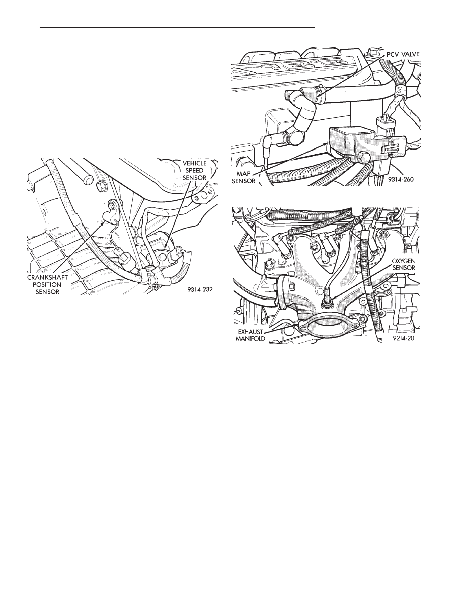
The crankshaft position sensor is located in the

transaxle housing, above the vehicle speed sensor (Fig.
9). The bottom of the sensor is positioned next to the
drive plate. The distance between the bottom of
sensor and the drive plate is critical to the op-
eration of the system. When servicing the crank-
shaft position sensor, refer to the Multi-Port Fuel
Injection Service Procedures—3.3L Engine sec-
tion in this Group.

MANIFOLD ABSOLUTE PRESSURE (MAP)
SENSOR—PCM INPUT

The PCM supplies 5 volts to the MAP sensor. The

MAP sensor converts intake manifold pressure into
voltage. The PCM monitors the MAP sensor output
voltage. As vacuum increases, MAP sensor voltage
decreases proportionately. Also, as vacuum decreases,
MAP sensor voltage increases proportionately.

During cranking, before the engine starts running,

the PCM determines atmospheric air pressure from
the MAP sensor voltage. While the engine operates, the
PCM determines intake manifold pressure from the
MAP sensor voltage. Based on MAP sensor voltage and
inputs from other sensors, the PCM adjusts spark
advance and the air/fuel mixture.

The MAP sensor (Fig. 10) mounts to the side of the

intake manifold, below the positive crankcase ventila-
tion (PCV) valve. The sensor connects electrically to
the PCM.

HEATED OXYGEN SENSOR (O

2

SENSOR)—PCM

INPUT

The O

2

sensor is located in the exhaust manifold and

provides an input voltage to the PCM. The input tells
the PCM the oxygen content of the exhaust gas (Fig.
11). The PCM uses this information to fine tune the
air-fuel ratio by adjusting injector pulse width.

The O

2

sensor produces voltages from 0 to 1 volt,

depending upon the oxygen content of the exhaust gas
in the exhaust manifold. When a large amount of
oxygen is present (caused by a lean air-fuel mixture),
the sensor produces a low voltage. When there is a
lesser amount present (rich air-fuel mixture) it pro-
duces a higher voltage. By monitoring the oxygen
content and converting it to electrical voltage, the
sensor acts as a rich-lean switch.

The oxygen sensor is equipped with a heating ele-

ment that keeps the sensor at proper operating tem-
perature during all operating modes. Maintaining cor-
rect sensor temperature at all times allows the system
to enter into closed loop operation sooner. Also, it
allows the system to remain in closed loop operation
during periods of extended idle.

In Closed Loop operation the PCM monitors the O

2

sensor input (along with other inputs) and adjusts the
injector pulse width accordingly. During Open Loop
operation the PCM ignores the O

2

sensor input. The

PCM adjusts injector pulse width based on prepro-
grammed (fixed) values and inputs from other sensors.

Fig. 9 Crankshaft Position Sensor Location

Fig. 10 Map Sensor

Fig. 11 Heated Oxygen Sensor—3.3L Engine

Ä

FUEL SYSTEMS

14 - 149

SPEED CONTROL—PCM INPUT

The speed control system provides four separate

voltages (inputs) to the PCM. The voltages corre-
spond to the On/Off, Set, and Resume.

The speed control ON voltage informs the PCM

that the speed control system has been activated.
The speed control SET voltage informs the PCM that
a fixed vehicle speed has been selected. The speed
control RESUME voltage indicates the previous fixed
speed is requested. The speed control OFF voltage
tells the PCM that the speed control system has been
deactivated. Refer to Group 8H for further speed con-
trol information.

TRANSAXLE PARK/NEUTRAL SWITCH—PCM
INPUT

The park/neutral switch is located on the transaxle

housing (Fig. 12). It provides an input to the PCM
indicating whether the automatic transaxle is in
Park or Neutral. This input is used to determine idle
speed (varying with gear selection) and ignition tim-
ing advance. The park neutral switch is sometimes
referred to as the neutral safety switch.

THROTTLE POSITION SENSOR (TPS)—PCM INPUT

The Throttle Position Sensor (TPS) is mounted on

the throttle body and connected to the throttle blade
shaft (Fig. 13). The TPS is a variable resistor that
provides the PCM with an input signal (voltage). The
signal represents throttle blade position. As the posi-
tion of the throttle blade changes, the resistance of
the TPS changes.

The PCM supplies approximately 5 volts to the

TPS. The TPS output voltage (input signal to the
PCM) represents the throttle blade position. The TPS
output voltage to the PCM varies from approxi-
mately 0.5 volt at minimum throttle opening (idle) to
3.5 volts at wide open throttle. Along with inputs
from other sensors, the PCM uses the TPS input to
determine current engine operating conditions. The

PCM also adjust fuel injector pulse width and igni-
tion timing based on these inputs.

VEHICLE SPEED AND DISTANCE INPUT—PCM
INPUT

The transaxle output speed sensor supplies the ve-

hicle speed and distance inputs to the PCM. The out-
put speed sensor is located on the side of the
transaxle (Fig. 12).

The speed and distance signals, along with a closed

throttle signal from the TPS, determine if a closed
throttle deceleration or normal idle condition (vehicle
stopped) exists. Under deceleration conditions, the
PCM adjusts the idle air control motor to maintain a
desired MAP value. Under idle conditions, the PCM
adjusts the idle air control motor to maintain a de-
sired engine speed.

AIR CONDITIONING (A/C) CLUTCH RELAY—PCM
OUTPUT

The PCM operates the air conditioning clutch relay

ground circuit (Fig. 14). The ignition switch supplies
battery voltage to the solenoid side of the relay.
When the A/C clutch relay energizes, battery voltage
powers the A/C compressor clutch.

With the engine operating and the blower motor

switch in the On position, the PCM cycles the air
conditioning clutch on and off when the A/C switch
closes. When the PCM senses low idle speeds or wide
open throttle through the throttle position sensor, it
de-energizes the A/C clutch relay. The relay contacts
open, preventing air conditioning clutch engagement.

GENERATOR FIELD—PCM OUTPUT

The PCM regulates the charging system voltage

Fig. 13 Throttle Position Sensor

Fig. 12 Park Neutral Switch—4-Speed Electronic

Automatic Transaxle

14 - 150

FUEL SYSTEMS

Ä

within a range of 12.9 to 15.0 volts. Refer to Group
8A for charging system information.

AUTO SHUTDOWN (ASD) RELAY AND FUEL PUMP
RELAY—PCM OUTPUT

The PCM operates the auto shutdown (ASD) relay

and fuel pump relay through one ground path. The
PCM operates the relays by switching the ground
path on and off. Both relays turn on and off at the
same time.

The ASD relay connects battery voltage to the fuel

injector and ignition coil. The fuel pump relay con-
nects battery voltage to the fuel pump and oxygen
sensor heating element.

The PCM turns the ground path off when the igni-

tion switch is in the Off position. Both relays are off.
When the ignition switch is in the On or Crank po-
sition, the PCM monitors the crankshaft position
sensor and camshaft position sensor signals to deter-
mine engine speed and ignition timing (coil dwell). If
the PCM does not receive the crankshaft position
sensor and camshaft position sensor signals when the
ignition switch is in the Run position, it de-energizes
both relays. When the relays are de-energized, bat-
tery voltage is not supplied to the fuel injector, igni-
tion coil, fuel pump and oxygen sensor heating
element.

The ASD relay and fuel pump relay are located in

the power distribution center (Fig. 14).

IDLE AIR CONTROL MOTOR—PCM OUTPUT

The idle air control motor is mounted on the throt-

tle body. The PCM operates the idle air control motor
(Fig. 13). The PCM adjusts engine idle speed through
the idle air control motor to compensate for engine
load or ambient conditions.

The throttle body has an air bypass passage that

provides air for the engine at idle (the throttle blade

is closed). The idle air control motor pintle protrudes
into the air bypass passage and regulates air flow
through it.

The PCM adjusts engine idle speed by moving the

idle air control motor pintle in and out of the bypass
passage. The adjustments are based on inputs the
PCM receives. The inputs are from the throttle posi-
tion sensor, crankshaft position sensor, coolant tem-
perature

sensor,

and

various

switch

operations

(brake, park/neutral, air conditioning). Deceleration
die out is also prevented by increasing airflow when
the throttle is closed quickly after a driving (speed)
condition.

CANISTER PURGE SOLENOID—PCM OUTPUT

Vacuum for the Evaporative Canister is controlled

by the Canister Purge Solenoid (Fig. 15). The sole-
noid is controlled by the PCM.

The PCM operates the solenoid by switching the

ground circuit on and off based on engine operating
conditions. When energized, the solenoid prevents
vacuum from reaching the evaporative canister.
When not energized the solenoid allows vacuum to
flow to the canister.

The PCM removes the ground to the solenoid when

the engine reaches a specified temperature and the
time delay interval has occurred. When the solenoid
is de-energized, vacuum flows to the canister purge
valve. Vapors are purged from the canister and flow
to the throttle body.

The purge solenoid will also be energized during

certain idle conditions, in order to update the fuel de-
livery calibration.

MALFUNCTION INDICATOR LAMP (CHECK ENGINE
LAMP)—PCM OUTPUT

The malfunction indicator lamp (instrument panel

Check Engine Lamp) comes on each time the ignition
key is turned ON and stays on for 3 seconds as a
bulb test. The malfunction indicator lamp warns the

Fig. 14 Relay Identification

Fig. 15 Canister Purge Solenoid

Ä

FUEL SYSTEMS

14 - 151

operator that the PCM has entered a Limp-in mode.
During Limp-in Mode, the PCM attempts to keep the
system operational. The malfunction indicator signals
the need for immediate service. In limp-in mode, the
PCM compensates for the failure of certain components
that send incorrect signals. The PCM substitutes for
the incorrect signals with inputs from other sensors.

Signals that can trigger the Malfunction Indi-

cator lamp (Check Engine Lamp).
• Engine Coolant Temperature Sensor

• Manifold Absolute Pressure Sensor

• Throttle Position Sensor

• Battery Voltage Input

• An Emission Related System (California vehicles)

• Charging system

The malfunction indicator (Check Engine Lamp) can

also display diagnostic trouble codes. Cycle the ignition
switch on, off, on, off, on, within five seconds and any
diagnostic trouble codes stored in the PCM will be
displayed. Refer to the 3.3L and 3.8L Multi-Port Fuel
Injection—On-Board Diagnostics section of this Group
for Diagnostic Trouble Code Descriptions.

DATA LINK CONNECTOR—PCM OUTPUT

The data link connector provides the technician with

the means to connect the DRBII scan tool to diagnosis
the vehicle.

TRANSAXLE CONTROL MODULE—PCM OUTPUT

The PCM supplies the following information to the

electronic automatic transaxle control module through
the CCD Bus:
• battery temperature

• brake switch input

• engine coolant temperature

• manifold absolute pressure (MAP)

• speed control information

ELECTRIC EGR TRANSDUCER (EET)
SOLENOID—PCM OUTPUT

The electronic EGR transducer (EET) contains an

electrically operated solenoid and a back-pressure
transducer (Fig. 16). The PCM operates the solenoid.
The PCM determines when to energize the solenoid.
Exhaust system back-pressure controls the transducer.

When the PCM energizes the solenoid, vacuum does

not reach the EGR valve. Vacuum flows to the EGR
valve when the PCM de-energizes the solenoid.

When exhaust system back-pressure becomes high

enough, it fully closes a bleed valve in the transducer.
When the PCM de-energizes the solenoid and back-
pressure closes the transducer bleed valve, vacuum
flows through the transducer to operate the EGR valve.

De-energizing the solenoid, but not fully closing the

transducer bleed hole (because of by low back-

pressure), varies the strength of vacuum applied to
the EGR valve. Varying the strength of the vacuum
changes the amount of EGR supplied to the engine.
This provides the correct amount of exhaust gas re-
circulation for different operating conditions.

FUEL INJECTORS—PCM OUTPUT

The fuel injectors are electrical solenoids (Fig. 17).

The injector contains a pintle that closes off an ori-
fice at the nozzle end. When electric current is sup-
plied to the injector, the armature and needle move a
short distance against a spring, allowing fuel to flow
out the orifice. Because the fuel is under high pres-
sure, a fine spray is developed in the shape of a hol-
low cone. The spraying action atomizes the fuel,
adding it to the air entering the combustion cham-
ber. The injectors are positioned in the intake mani-
fold.

The fuel injectors are operated by the PCM. They

are energized in a sequential order during all engine
operating conditions except start up. The PCM ini-
tially energizes all injectors at the same time. Once

Fig. 16 Electric EGR Transducer (EET) Assembly

Fig. 17 Fuel Injector—3.3L Engine

14 - 152

FUEL SYSTEMS

Ä


Content   ..  56  57  58  59   ..