Chrysler Le Baron, Dodge Dynasty, Plymouth Acclaim. Manual - part 48


  Index      Chrysler     Chrysler Le Baron, Dodge Dynasty, Plymouth Acclaim - service repair manual 1993 year


Search            


Content   ..  46  47  48  49   ..


Chrysler Le Baron, Dodge Dynasty, Plymouth Acclaim. Manual - part 48


FUEL INJECTOR RAIL ASSEMBLY

WARNING: THE 2.2L TURBO III FUEL SYSTEM IS
UNDER A CONSTANT PRESSURE OF APPROXI-
MATELY 380 KPA (55 PSI). PERFORM FUEL PRES-
SURE RELEASE PROCEDURE BEFORE SERVICING
THE FUEL RAIL OR FUEL INJECTORS.

REMOVAL

(1) Perform fuel system pressure release procedure.
(2) Disconnect negative battery cable.

CAUTION: Place a shop towel should under the fuel
hoses to catch any fuel spillage.

(3) Remove quick connect fittings from the chassis

fuel tubes (Fig. 7). Refer to Quick Connect Fittings
in the Fuel Delivery Section of this manual.

(4) Disconnect the vacuum hose from the fuel pres-

sure regulator (Fig. 8).

(5) Disconnect the fuel injector wiring harness

from the main harness.

(6) Place oil separator bracket out of the way and

remove the fuel rail support bracket screws.

(7) Remove the fuel rail and injector assembly by

pulling rail so that the injectors come straight out of
their ports. Do not damage the rubber injector
O-rings after removing the fuel rail.

Do not remove fuel injectors until fuel rail assem-

bly has been completely removed from the vehicle.

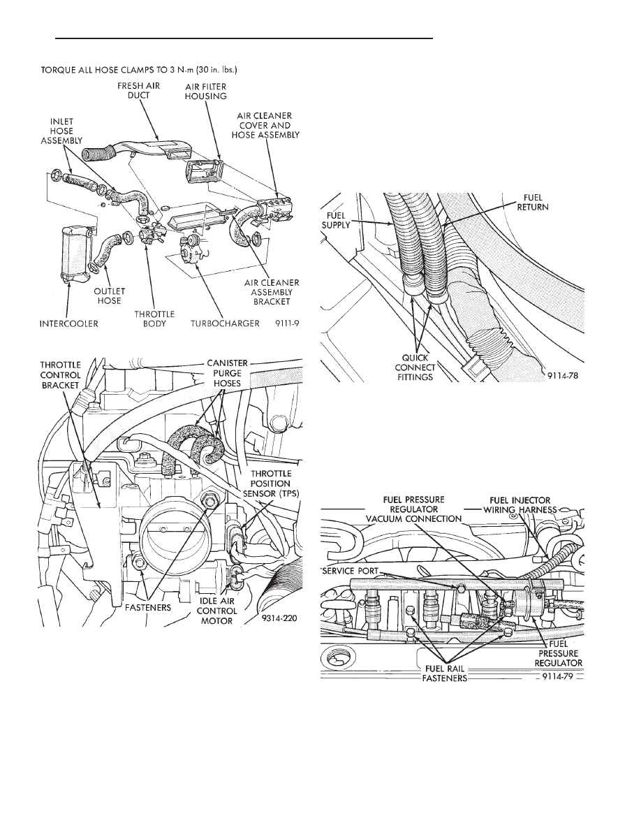
Fig. 7 Quick Connect Fittings

Fig. 8 Fuel Rail Fasteners

Fig. 5 Air Cleaner Assembly

Fig. 6 Throttle Body Assembly

Ä

FUEL SYSTEMS

14 - 109

(8) Cover or plug the injector ports with while ser-

vicing the injectors (Fig. 9).

INSTALLATION

(1) Ensure the injectors are seated into the re-

ceiver cup, with the lock ring in place.

(2) Ensure the injector wiring connectors are fully

inserted into the fuel injectors.

(3) Make sure the injector holes are clean and all

plugs have been removed (Fig. 9).

(4) Lubricate the injector O-rings with a drop of

clean engine oil.

(5) Install the injector assemblies into their holes

and install the attaching bolts. Draw the fuel rail as-
sembly evenly into the intake manifold, making sure
each injector enters its own hole. The oil separator
bracket must be on top of the fuel rail bracket (Fig.
8).

(6) Once all injectors are evenly seated, tighten the

fuel rail attaching bolts to 23 N

Im (200 in. lbs.)

torque.

(7) Connect the fuel injector wiring harness to the

main harness.

(8) Lubricate the ends of the chassis tubes with

clean 30 weight engine oil.

(9) Connect fuel hose quick connect fittings to the

chassis fuel tubes. Pull on the fittings to ensure com-
plete connection.

Refer to Quick Connect Fittings in the Fuel Deliv-

ery Section of this group.

(10) Connect the vacuum hose to the fuel pressure

regulator.

(11) Connect negative cable to battery.

CAUTION: When using the ASD Fuel System Test,
the Auto Shutdown (ASD) Relay remains energized
for either 7 minutes, until the test is stopped, or un-
til the ignition switch is turned to the Off position.

(12) With the DRBII scan tool the ASD Fuel Sys-

tem Test to pressurize the fuel system to check for
leaks.

FUEL INJECTORS

Remove the fuel rail to service the injectors. Refer

to Fuel Injector Rail Assembly in this section.

REMOVAL

(1) Disconnect injector electrical connector from in-

jector. (Fig. 10).

(2) Position fuel rail assembly so that the fuel in-

jectors are easily accessible (Fig. 11).

(3) Remove injector lock ring off the fuel rail and

injector. Pull injector straight out of fuel rail receiver
cup (Fig. 11).

(4) Check injector O-ring for damage. If O-ring is

damaged, it must be replaced. If injector is reused, a
protective cap must be installed on the injector tip to
prevent damage.

(5) Repeat for remaining injectors.

Fig. 9 Fuel Injector Ports

Fig. 10 Fuel Rail and Injector Assembly

Fig. 11 Servicing Fuel Injectors

14 - 110

FUEL SYSTEMS

Ä

INSTALLATION

(1) Before installing an injector, the rubber O-ring

must be lubricated with a drop of clean engine oil to aid
in installation.

(2) Being careful not to damage the O-ring, install

injector top end into fuel rail receiver cup.

(3) Install injector lock ring by sliding open end into

slot of the injector and onto the receiver cup ridge into
the side slots of ring (Fig. 11).

(4) Repeat steps for remaining injectors.
(5) Install injector wiring harness to injectors. Place

harness into retaining clips.

FUEL PRESSURE REGULATOR

WARNING: THE 2.2L TURBO III FUEL SYSTEM IS
UNDER A CONSTANT PRESSURE OF APPROXI-
MATELY 380 KPA (55 PSI). PERFORM FUEL PRES-
SURE RELEASE PROCEDURE BEFORE SERVICING
THE FUEL PRESSURE REGULATOR.

REMOVAL

(1) Perform fuel system pressure release procedure.
(2) Disconnect negative cable from battery.
(3) Disconnect vacuum hose from fuel pressure regu-

lator (Fig. 12).

Place a shop towel under fuel pressure regula-

tor to absorb any fuel spillage.

(4) Loosen fuel hose clamp and remove fuel return

hose.

(5) Remove fuel pressure regulator mounting nuts.

Remove fuel pressure regulator from rail (Fig. 12).
Check O-Ring for damage. If O-Ring is damaged it
must be replaced.

INSTALLATION

(1) Lubricate O-ring with a drop of clean engine oil.

Install O-ring into the receiver cup on fuel rail.

(2) Install fuel pressure regulator mounting nuts.

Tighten nuts to 7 N

Im (65 in. lbs.) torque.

(3) Connect fuel return hose to pressure regulator.

Tighten hose clamp to 1 N

Im (10 in. lbs.) torque (Fig.

12).

(4) Install vacuum hose on fuel pressure regulator.
(5) Connect negative cable to battery.

CAUTION: When using the ASD Fuel System Test,
the Auto Shutdown (ASD) Relay remains energized
for either 7 minutes, until the test is stopped, or un-
til the ignition switch is turned to the Off position.

(6) With the DRBII scan tool the ASD Fuel System

Test to pressurize system and check for leaks.

MANIFOLD ABSOLUTE PRESSURE (MAP) SENSOR
SERVICE

(1) Remove vacuum hose from MAP sensor (Fig.

13)

(2) Remove MAP sensor mounting screws (Fig. 13).
(3) Remove electrical connector. Remove sensor.
(4) Reverse the above procedure for installation.

WASTEGATE AND CANISTER PURGE SOLENOID
SERVICE

(1) Remove vacuum hoses from sensors (Fig. 14).
(2) Disconnect electrical connector from solenoids

(Fig. 14).

(3) Remove solenoid pack mounting nut. Remove

solenoid pack.

(4) Depress tab on top of solenoid to be replaced

and slide the solenoid downward out of mounting
bracket.

(5) Reverse above procedure to install.

PCM SERVICE

(1) Remove air cleaner duct from PCM.
(2) Remove battery.
(3) Remove PCM mounting screws (Fig. 15).
(4) Disconnect the 60-way wiring connector. Re-

move the PCM.

(5) Reverse the above procedure for installation.

Fig. 13 Manifold Absolute Pressure Sensor

Fig. 12 Servicing Fuel Pressure Regulator

Ä

FUEL SYSTEMS

14 - 111

HEATED OXYGEN SENSOR (O

2

SENSOR)

The oxygen sensor is installed in the exhaust man-

ifold (Fig. 16).

CAUTION: Do not pull on the oxygen sensor wires
when disconnecting the electrical connector.

WARNING: THE EXHAUST MANIFOLD MAY BE EX-
TREMELY HOT. USE CARE WHEN SERVICING THE
OXYGEN SENSOR.

(1) Disconnect oxygen sensor electrical connector.
(2) Remove sensor using Tool C-4907 (Fig. 17).

Slightly tightening the sensor can ease removal.

When the sensor is removed, the exhaust manifold

threads must be cleaned with an 18 mm X 1.5 + 6E
tap. If using original sensor, coat the threads with
Loctite 771-64 anti-seize compound or equivalent.
New sensors are packaged with compound on the
threads and do not require additional compound.
Tighten the sensor to 27 N

Im (20 ft. lbs.) torque.

Fig. 14 Solenoid Mounting

Fig. 15 PCM

Fig. 16 Heated Oxygen Sensor

Fig. 17 Oxygen Sensor Socket

14 - 112

FUEL SYSTEMS

Ä


Content   ..  46  47  48  49   ..