Chrysler Le Baron, Dodge Dynasty, Plymouth Acclaim. Manual - part 26


  Index      Chrysler     Chrysler Le Baron, Dodge Dynasty, Plymouth Acclaim - service repair manual 1993 year


Search            


Content   ..  24  25  26  27   ..


Chrysler Le Baron, Dodge Dynasty, Plymouth Acclaim. Manual - part 26


INSTALLATION

WARNING: FUEL PRESSURE RELIEF/ROLLOVER
VALVES DESIGNED FOR GASOLINE ONLY VEHI-
CLES CANNOT BE USED ON FLEXIBLE FUEL AA-
BODY VEHICLES. WHEN SERVICING THE FUEL
SYSTEM OF A FLEXIBLE FUEL VEHICLE, ONLY
USE ORIGINAL EQUIPMENT OR EQUIVALENT RE-
PLACEMENT COMPONENTS.

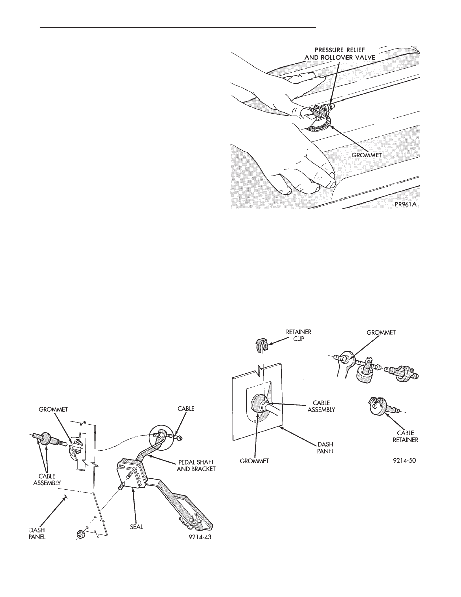
(1) Install the rubber grommet in the fuel tank by

working it around the curled lip of the tank (Fig. 13).

CAUTION: Only use power steering fluid to lubri-

cate the pressure relief/rollover valve grommet.

(2) Lightly lubricate the grommet with power

steering fluid only and push the valve downward into
the grommet. Twist valve until properly positioned.

(3) Install fuel tank (refer to fuel tank installa-

tion).

ACCELERATOR PEDAL AND THROTTLE CABLE

INDEX

page

page

Accelerator Pedal

. . . . . . . . . . . . . . . . . . . . . . . . 21

Throttle Cable

. . . . . . . . . . . . . . . . . . . . . . . . . . . 22

ACCELERATOR PEDAL

CAUTION: When servicing the accelerator pedal,
throttle cable or speed control cable, do not dam-
age or kink the control cable core wire.

REMOVAL

(1) Working from the engine compartment, hold

the throttle body throttle lever in the wide open po-
sition. Remove the throttle cable from the throttle
body cam.

(2) From inside the vehicle, hold up the pedal and

remove the cable retainer and throttle cable from the
upper end of the pedal shaft (Fig. 1 and Fig. 2).

(3) Working from the engine compartment, remove

nuts from accelerator pedal assembly studs (Fig. 1).
Remove assembly from vehicle.

INSTALLATION

(1) Position accelerator pedal assembly on dash

panel. Install retaining nuts. Tighten retaining nuts
to 12 N

Im (105 in. lbs.) torque.

Fig. 1 Accelerator Pedal and Throttle Cable—Front

View

Fig. 13 Installing Pressure Relief/Rollover Valve

Fig. 2 Accelerator Pedal and Throttle Cable—Rear

View

Ä

FUEL SYSTEMS

14 - 21

(2) From inside the vehicle, hold up the pedal and

install the throttle cable and cable retainer in the
upper end of the pedal shaft.

(3) From the engine compartment, hold the throt-

tle body lever in the wide open position and install
the throttle cable.

THROTTLE CABLE

REMOVAL

(1) Working from the engine compartment, hold

throttle lever in the wide open position and remove
the throttle cable from the throttle body cam (Fig. 3,
4, 5, 6 and 7).

(2) From inside the vehicle, hold the throttle pedal

up and remove the cable retainer and cable from up-
per end of pedal shaft (Fig. 1 and Fig. 2).

(3) Remove retainer clip from throttle cable and

grommet at the dash panel (Fig. 2).

(4) From the engine compartment, pull the throttle

cable out of the dash panel grommet. The grommet
should remain in the dash panel.

(5) Remove the throttle cable from the throttle

bracket by carefully compressing both retaining tabs
simultaneously. Gently pull throttle cable from throt-
tle bracket.

INSTALLATION

(1) From the engine compartment, push the hous-

ing end fitting into the dash panel grommet.

(2) Install cable housing (throttle body end) into

the cable mounting bracket on the engine.

(3) From inside the vehicle, hold up pedal and feed

throttle cable core wire through hole in upper end of
the pedal shaft. Install cable retainer (Fig. 2).

(4) Install cable retainer clip (Fig. 2).
(5) From the engine compartment, rotate the throt-

tle lever to the wide open position and install throt-
tle cable.

Fig. 3 Throttle Cable Attachment to Throttle

Body—2.2L/2.5L TBI Engine

Fig. 4 Throttle Cable Attachment to Throttle

Body—2.5L MPI Flexible Fuel Engine

Fig. 5 Throttle Cable Attachment to Throttle

Body—Turbo III Engine

Fig. 6 Throttle Cable Attachment to Throttle

Body—3.0L Engine

14 - 22

FUEL SYSTEMS

Ä

Fig. 7 Throttle Cable Attachment to Throttle

Body—3.3L and 3.8L Engines

Ä

FUEL SYSTEMS

14 - 23

2.2L/2.5L SINGLE POINT FUEL INJECTION—SYSTEM OPERATION

INDEX

page

page

Air Conditioning (A/C) Clutch Relay—PCM Output

. 28

Air Conditioning Switch Sense—PCM Input

. . . . . 26

Auto Shutdown (ASD) Relay and Fuel Pump

Relay—PCM Output

. . . . . . . . . . . . . . . . . . . . . 29

Battery Voltage—PCM Input

. . . . . . . . . . . . . . . . 26

Brake Switch—PCM Input

. . . . . . . . . . . . . . . . . . 26

EVAP Canister Purge Solenoid—PCM Output

. . . 29

CCD Bus

. . . . . . . . . . . . . . . . . . . . . . . . . . . . . . 25

Coolant Temperature Sensor—PCM Input

. . . . . . 26

Data Link Connector—PCM Output

. . . . . . . . . . . 30

Distributor (Hall Effect) Pick-Up—PCM Input

. . . . 26

Electric Electronic Gas Recirculation—PCM Output

. 30

Fuel Injector—PCM Output

. . . . . . . . . . . . . . . . . 31

Fuel Pressure Regulator

. . . . . . . . . . . . . . . . . . . 33

General Information

. . . . . . . . . . . . . . . . . . . . . . . 24

Generator Field—PCM Output

. . . . . . . . . . . . . . . 31

Heated Oxygen Sensor (O

2

Sensor)—PCM Input

27

Idle Air Control Motor—PCM Output

. . . . . . . . . . 29

Ignition Coil—PCM Output

. . . . . . . . . . . . . . . . . . 31

Malfunction Indicator Lamp (Check Engine)—PCM

Output

. . . . . . . . . . . . . . . . . . . . . . . . . . . . . . . 30

Manifold Absolute Pressure (MAP) Sensor—PCM

Input

. . . . . . . . . . . . . . . . . . . . . . . . . . . . . . . . 27

Modes of Operation

. . . . . . . . . . . . . . . . . . . . . . . 32

Part Throttle Unlock Solenoid—PCM Output

. . . . 31

Powertrain Control Module

. . . . . . . . . . . . . . . . . 25

Radiator Fan Relay—PCM Output

. . . . . . . . . . . . 31

Speed Control Solenoids—PCM Output

. . . . . . . . 31

Speed Control—PCM Input

. . . . . . . . . . . . . . . . . 27

System Diagnosis

. . . . . . . . . . . . . . . . . . . . . . . . 25

Tachometer—PCM Output

. . . . . . . . . . . . . . . . . . 32

Throttle Body

. . . . . . . . . . . . . . . . . . . . . . . . . . . . 33

Throttle Position Sensor (TPS)—PCM Input

. . . . . 28

Transaxle Park/Neutral Switch—PCM Input

. . . . . 28

Vehicle Speed Sensor—PCM Input

. . . . . . . . . . . 28

GENERAL INFORMATION

The computer regulated, Electronic Fuel Injection

System (Fig. 1) provides a precise air/fuel ratio for
all driving conditions. The fuel injection system is
controlled by the powertrain control module (PCM).

The PCM is a pre-programmed digital computer. The

PCM regulates ignition timing, air-fuel ratio, emission
control devices, cooling fan, charging system, speed con-
trol, and idle speed. The PCM can adapt its requirement
to meet changing operating conditions.

Fig. 1 Electronic Fuel Injection Components

14 - 24

FUEL SYSTEMS

Ä


Content   ..  24  25  26  27   ..