Chrysler Le Baron, Dodge Dynasty, Plymouth Acclaim. Manual - part 23


  Index      Chrysler     Chrysler Le Baron, Dodge Dynasty, Plymouth Acclaim - service repair manual 1993 year


Search            


Content   ..  21  22  23  24   ..


Chrysler Le Baron, Dodge Dynasty, Plymouth Acclaim. Manual - part 23


(2) Remove fuel pump and O-ring seal from tank.

Discard old seal.

FUEL PUMP MODULE INSTALLATION

WARNING: FUEL PUMP MODULES DESIGNED FOR
GASOLINE ONLY VEHICLES CANNOT BE USED ON
FLEXIBLE FUEL AA-BODY VEHICLES. WHEN SER-
VICING THE FUEL SYSTEM OF A FLEXIBLE FUEL
VEHICLE, ONLY USE ORIGINAL EQUIPMENT OR
EQUIVALENT REPLACEMENT COMPONENTS.

(1) Wipe seal area of tank clean and place a new

O-ring seal in position on pump.

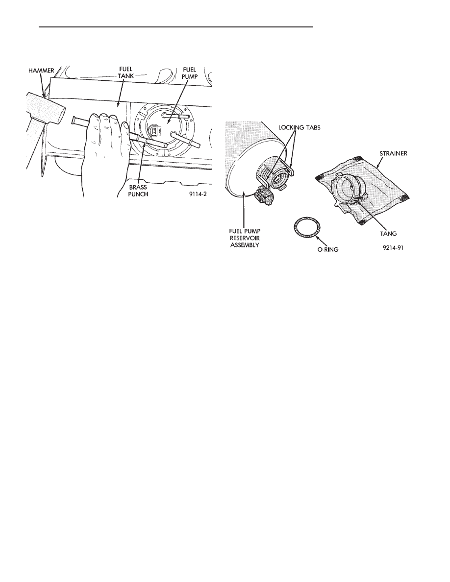
(2) Position fuel pump in tank with locking ring.
(3) Using a hammer and brass drift, drive ring

around in clockwise direction to lock pump in place.

CAUTION: Over tightening the pump lock ring

may result in a leak.

(4) Install tank. Refer to the Fuel Tank Section in

this Group.

FUEL PUMP STRAINER SERVICE

WARNING: RELEASE FUEL SYSTEM PRESSURE
BEFORE SERVICING FUEL SYSTEM COMPONENTS.
WHEN

SERVICING

FLEXIBLE

FUEL

VEHICLES,

WEAR METHANOL RESISTANT GLOVES AND EYE
PROTECTION AND AVOID BREATHING FUMES. DO
NOT ALLOW METHANOL/GASOLINE MIXTURES TO
CONTACT SKIN. SERVICE VEHICLES IN WELL VEN-
TILATED AREAS AND AVOID IGNITION SOURCES.
NEVER SMOKE WHILE SERVICING THE VEHICLE.

REMOVAL

(1) Remove fuel pump module. Refer to Fuel Pump

Module in this section.

(2) Bend locking tabs on fuel pump reservoir as-

sembly to clear locking tangs on the fuel pump
strainer (Fig. 12).

(3) Pull strainer off.
(4) Remove strainer O-ring from the fuel pump

reservoir body.

(5) Remove any contaminants by washing the in-

side of the fuel tank.

INSTALLATION

WARNING: FUEL STRAINERS (AND O-RINGS) DE-
SIGNED FOR GASOLINE ONLY VEHICLES CANNOT
BE USED ON FLEXIBLE FUEL AA-BODY VEHICLES.
WHEN SERVICING THE FUEL SYSTEM OF A FLEX-
IBLE FUEL VEHICLE, ONLY USE ORIGINAL EQUIP-
MENT

OR

EQUIVALENT

REPLACEMENT

COMPONENTS.

(1) Lubricate the strainer O-ring with Mopar Sili-

cone Spray Lube.

(2) Insert strainer O-ring into outlet of strainer so

that it sits evenly on the step inside the outlet.

(3) Push strainer onto the inlet of the fuel pump

reservoir body. Make sure the locking tabs on the
reservoir body lock over the locking tangs on the
strainer.

(4) Install fuel pump module. Refer to Fuel Pump

Module in this section.

FUEL FILTER—ALL VEHICLES

WARNING: RELEASE FUEL SYSTEM PRESSURE
BEFORE SERVICING FUEL SYSTEM COMPONENTS.
WHEN

SERVICING

FLEXIBLE

FUEL

VEHICLES,

WEAR METHANOL RESISTANT GLOVES AND EYE
PROTECTION AND AVOID BREATHING FUMES. DO
NOT ALLOW METHANOL/GASOLINE MIXTURES TO
CONTACT SKIN. SERVICE VEHICLES IN WELL VEN-
TILATED AREAS AND AVOID IGNITION SOURCES.
NEVER SMOKE WHILE SERVICING THE VEHICLE.

Fig. 11 Fuel Pump Service

Fig. 12 Fuel Strainer Service

Ä

FUEL SYSTEMS

14 - 9

REMOVAL

(1) Perform the Fuel System Pressure Release pro-

cedure.

(2) ) Remove the fuel filter retaining screw (Fig.

13). Remove fuel filter from mounting plate.

(3) Wrap a shop towel around hoses to absorb fuel.

Remove quick-connect fittings at filter and fuel supply
tube. Refer to Quick-Connect Fittings in this section.

INSTALLATION

WARNING: FUEL FILTERS DESIGNED FOR GASO-
LINE ONLY VEHICLES CANNOT BE USED ON
FLEXIBLE FUEL AA-BODY VEHICLES. WHEN SER-
VICING THE FUEL SYSTEM OF A FLEXIBLE FUEL
VEHICLE, ONLY USE ORIGINAL EQUIPMENT OR
EQUIVALENT REPLACEMENT COMPONENTS.

(1) Connect quick-connect fuel fittings to the filter

and fuel supply line. Refer to Quick-Connect Fittings
in this section.

(2) Position filter assembly on mounting plate and

tighten mounting screw to 8 N

Im (75 in. lbs.) torque.

CAUTION: When using the ASD Fuel System Test,
the Auto Shutdown (ASD) Relay remains energized
for either 7 minutes, until the test is stopped, or un-
til the ignition switch is turned to the Off position.

(3) Place the ignition key in the ON position. Us-

ing the DRBII scan tool, access ASD Fuel System
Test. The ASD Fuel System Test will activate the
fuel pump and pressurize the system. Inspect for
leaks.

FUEL HOSES, CLAMPS, AND QUICK CONNECT
FITTINGS

HOSES AND CLAMPS

WARNING: RELEASE FUEL SYSTEM PRESSURE
BEFORE SERVICING FUEL SYSTEM COMPONENTS.

WHEN

SERVICING

FLEXIBLE

FUEL

VEHICLES,

WEAR METHANOL RESISTANT GLOVES AND EYE
PROTECTION AND AVOID BREATHING FUMES. DO
NOT ALLOW METHANOL/GASOLINE MIXTURES TO
CONTACT SKIN. SERVICE VEHICLES IN WELL VEN-
TILATED AREAS AND AVOID IGNITION SOURCES.
NEVER SMOKE WHILE SERVICING THE VEHICLE.

WARNING: FUEL SYSTEM HOSES AND TUBES DE-
SIGNED FOR GASOLINE ONLY VEHICLES CANNOT
BE USED ON FLEXIBLE FUEL VEHICLES. WHEN
SERVICING THE FUEL SYSTEM OF A FLEXIBLE
FUEL VEHICLE, ONLY USE ORIGINAL EQUIPMENT
OR EQUIVALENT REPLACEMENT COMPONENTS.

Inspect all hose connections (clamps and quick con-

nect fittings) for completeness and make sure they
are not leaking. Hoses that are cracked, scuffed,
swelled, rub against other vehicle components or
show any sign of wear, should be replaced.

When installing hoses, route them away from compo-

nents they could rub against. Avoid contact with clamps
or other components that cause abrasions or scuffing.
Ensure rubber hoses are properly routed and avoid heat
sources.

The clamps have rolled edge to prevent the clamp

from cutting into the hose. Only use clamps that are
original equipment or equivalent. Other types of clamps
may cut into the hoses and cause high pressure fuel
leaks. Tighten hose clamps to 1 N

Im (10 in. lbs.) torque.

QUICK CONNECT FITTINGS

Most fuel lines have quick connect fittings. The fit-

tings speed up the installation and removal of fuel
lines (Fig. 14).

Quick connect fittings consist of a metal casing, a

black plastic release ring, a metal locking retainer,
and internal O-rings.

METAL QUICK CONNECT FITTINGS

The fuel filter and fuel rail use steel quick-connect

fittings. The fitting contains non-serviceable sealed
O-rings. The fittings contain a plastic disconnect tool.

The quick-connect fitting consists of the O-rings, cas-

ing, disconnect tool and a retainer (Fig. 14). When the

Fig. 13 Fuel Filter

Fig. 14 Metal Quick-Connect Fittings

14 - 10

FUEL SYSTEMS

Ä

fuel tube enters the fitting, the retainer locks the shoul-
der of the nipple in place and the O-rings seal the tube.

CAUTION: Quick-connect fittings are not serviced
separately. Do not attempt to repair damaged quick-
connect fittings or fuel tubes. Replace the complete
fuel tube/quick-connect fitting assembly.

When installing fuel tubes, route them in the holders

along the frame rail, fuel tank and the rear of the en-
gine.

REMOVAL

WARNING: RELEASE FUEL SYSTEM PRESSURE
BEFORE SERVICING FUEL SYSTEM COMPONENTS.
WHEN

SERVICING

FLEXIBLE

FUEL

VEHICLES,

WEAR METHANOL RESISTANT GLOVES AND EYE
PROTECTION AND AVOID BREATHING FUMES. DO
NOT ALLOW METHANOL/GASOLINE MIXTURES TO
CONTACT SKIN. SERVICE VEHICLES IN WELL VEN-
TILATED AREAS AND AVOID IGNITION SOURCES.
NEVER SMOKE WHILE SERVICING THE VEHICLE.

(1) Disconnect negative cable from the battery.
(2) Perform the Fuel Pressure Release Procedure.

Refer to the Fuel Pressure Release Procedure in this
section.

(3) Remove any loose dirt from quick connect fit-

tings.

WARNING: WRAP SHOP TOWELS AROUND HOSES
TO CATCH ANY FUEL SPILLAGE.

(4) Push the quick connect fitting toward the fuel

tube while depressing the built-in release tool. Then
slightly twist the fitting and pull it off the fuel tube
(Fig. 14).

(5) Cover the fitting to prevent contamination.

TUBE/FITTING SERVICE

WARNING: RELEASE FUEL SYSTEM PRESSURE
BEFORE SERVICING FUEL SYSTEM COMPONENTS.
WHEN

SERVICING

FLEXIBLE

FUEL

VEHICLES,

WEAR METHANOL RESISTANT GLOVES AND EYE
PROTECTION AND AVOID BREATHING FUMES. DO
NOT ALLOW METHANOL/GASOLINE MIXTURES TO
CONTACT SKIN. SERVICE VEHICLES IN WELL VEN-
TILATED AREAS AND AVOID IGNITION SOURCES.
NEVER SMOKE WHILE SERVICING THE VEHICLE.

If a quick connect fitting needs service, the follow-

ing procedure must be followed:

(1) Disconnect the battery negative battery cable.
(2) Perform the Fuel System Pressure Release Pro-

cedure.

WARNING: WRAP SHOP TOWELS AROUND HOSES
TO CATCH ANY FUEL SPILLAGE.

(3) Remove the quick connect fitting from the fuel

tube by pushing in on the plastic ring located on the
end of the fitting. Gently pull the fitting from the
fuel tube.

(4) Cut off the crimp ferrules at each end of the

hose, taking care not to damage the quick connect
fitting or the fuel tube.

(5) Discard the ferrules and hose.

WARNING: FUEL SYSTEM HOSES AND TUBES DE-
SIGNED FOR GASOLINE ONLY VEHICLES CANNOT
BE USED ON FLEXIBLE FUEL VEHICLES. WHEN
SERVICING THE FUEL SYSTEM OF A FLEXIBLE
FUEL VEHICLE, ONLY USE ORIGINAL EQUIPMENT
OR EQUIVALENT REPLACEMENT COMPONENTS.

(6) Replace the hose using original equipment or

equivalent hose.

(7) Attach the replacement hose to the quick con-

nect fitting and fuel tube using the correct hose
clamps (Fig. 15). Original equipment hose clamps
have a special rolled edge construction to prevent the
edge of the clamp cutting into the hose. Only original
equipment clamps or equivalent may be used in this
system. Other types of clamps may cut into the hoses
and cause high pressure fuel leaks.

(8) Tighten hose clamps to 1 N

Im (10 in. lbs.)

torque.

CAUTION: When using the ASD Fuel System Test,
the Auto Shutdown (ASD) Relay remains energized
for either 7 minutes, until the test is stopped, or un-
til the ignition switch is turned to the Off position.

(9) Use the DRBII scan tool ASD Fuel System Test

to pressurize the fuel system. Check for leaks.

CHASSIS FUEL TUBES

Figures 16 and 17 show fuel system component lo-

cations and chassis fuel tube routings.

Fig. 15 Quick Connect Fuel Fittings

Ä

FUEL SYSTEMS

14 - 11

Fig.

16

Fuel

T

ank,

Filter

,

and

Chassis

Line

Routing—Except

Flexible

Fuel

AA-Body

14 - 12

FUEL SYSTEMS

Ä


Content   ..  21  22  23  24   ..