Chery Tiggo. Manual - part 346


  Index      Chery     Chery Tiggo - service repair manual 2009 year


Search            


Content   ..  344  345  346  347   ..


Chery Tiggo. Manual - part 346


7. Remove the exhaust pipe assembly mounting bolts

(1).
(Tighten: Exhaust pipe assembly mounting bolts to
25 ± 3 N·m)

8. Remove the exhaust pipe assembly (See Exhaust Pipe Assembly Removal & Installation in Section 07 Exhaust).

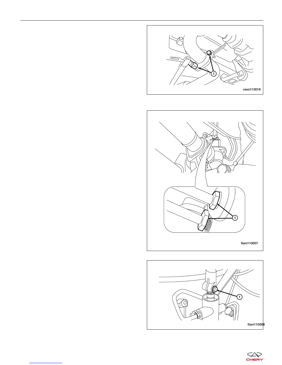
9. Remove the high pressure and low pressure lines

(1) from the steering gear.
(Tighten: High pressure line to steering gear 27 -
33 N·m)
(Tighten: Low pressure line to steering gear 27 - 33
N·m)

10. Remove the intermediate shaft coupling bolt (1) at

the steering gear.
(Tighten: Intermediate shaft coupling bolt to 25 - 30
N·m)

ON-VEHICLE SERVICE

VISM110016

LTSM110007

LTSM110008


11. On each side of the steering gear, remove the nut

(1) attaching the outer tie rod end to the steering
knuckle.
(Tighten: Outer tie rod end nut to 32 - 38 N·m)

12. Using special tool CH-10002, separate the outer tie

rod ends from both steering knuckles.

13. Remove the wheel speed sensor mounting bolt (1).

(Tighten: Wheel speed sensor mounting bolt to
10 ± 1 N·m)

14. Remove the wheel speed sensor and set it aside.

ON-VEHICLE SERVICE

LTSM110034

LTSM110027

LTSM100045

11


15. Remove the bolts (1) between the steering gear

and the sub-frame.
(Tighten: Steering gear and sub-frame bolt to 70 -
80 N·m)

16. Support the engine using a suitable tool.

17. Remove the engine front and rear mounts (See Engine Mounts Removal & Installation in Section 02 Engine).

18. Remove the sub-frame mounting bolts (1) (4 total)

between the sub-frame assembly and the vehicle
body.
(Tighten: Sub-frame mounting bolts to 180 ± 15
N·m)

NOTE :
Before removing the front suspension sub-frame from the vehicle, the location of the sub-frame must be marked on
the body of the vehicle. Do this so the sub-frame can be relocated, upon reinstallation, against the body of vehicle in
the same location as before removal. If the front suspension sub-frame is not reinstalled in exactly the same location
as before removal, the preset front wheel alignment settings (caster and camber) may be lost.

19. Using a jack, slowly lower the sub-frame enough to access the intermediate shaft coupling at the steering gear

pinion shaft.

20. Remove the steering gear assembly.

21. Installation is in the reverse order of removal.

Installation Notes:
• After installing the new steering gear, perform a front end alignment procedure to reset the toe-in (See Front

Wheel Alignment in Section 10 Suspension).

ON-VEHICLE SERVICE

LTSM100024

LTSM100044


Tie Rod

Removal & Installation

NOTE :
The following special tool is required to perform the repair procedure:
• CH-10002 - Ball Joint Separator

1. Raise and support the vehicle.

2. Remove the wheel mounting nuts and the wheel assembly.

(Tighten: Wheel mounting nuts to 110 N·m)

3. Loosen the tie rod jam nut (1).

(Tighten: Tie rod jam nut to 15 N·m)

4. Remove the nut (1) attaching the outer tie rod end

to the steering knuckle.
(Tighten: Outer tie rod end nut to 32 - 38 N·m)

5. Using special tool CH-10002, separate the outer tie rod end from the steering knuckle.

6. Remove the outer tie rod end from the steering rack.

NOTE :
When removing the outer tie rod end, count the number of revolutions when removing. This will aid in installation,
getting the toe setting close to where it needs to be when setting the final toe-in wheel alignment.

7. Installation is in the reverse order of removal.

Installation Notes:
• After installing the new tie rod end, perform a front end alignment procedure to reset the toe-in (See Front

Wheel Alignment in Section 10 Suspension).

ON-VEHICLE SERVICE

VISM100021

LTSM110034

11


Content   ..  344  345  346  347   ..