Chery SQR 7160 sedan. Manual - part 30


  Index      Chery     Chery SQR 7160 sedan - service repair manual


Search            


Content   ..  28  29  30  31   ..


Chery SQR 7160 sedan. Manual - part 30


CAC Gasoline Engine Maintenance And Servicing Manual 

38 

 
Installation of the piston and rod assembly: 
 
        Apply  engine  oil  on  piston,  piston  ring  and  cylinder  bore. 
Stagger 120°among the first    compression ring, the second ring 
and oil ring cotter, then install piston rod into cylinder bore. push 
the piston an rod assembly by hammer into the cylinder bore. 
——Apply  engine  oil  on  the  connecting  rod  bushing.  Mount 
connecting rod cap. Retain connecting rod body and cap with two 
elastic retaining pins. 
——Tighten connecting rod bolt  to 30—36Nm. apply  engine  oil 
on the bolt head and bolt threads before installation. 
——The side play of big end is 0.092—0.268mm。 
 
10】The  removal  and  installation  of  flywheel  assembly  and 
carrier assembly of real 
crankshaft oil seal     

1). The removal and installation of flywheel assembly 
removal: 
——Remove six M10 bolts and replace bolts. 
——Remove  flywheel.  Check  if  there  is  crack  in  the 
surface  of  clutch  plate.  Check  ring  gear  teeth  for 
crack ,wear, pitting . 
Installation: 
——The  press  fit  clearance  of  gear  ring  and  flywheel  is 
0.48—0.86mm.  The  gear  ring  should  be  pressed  when 
heated to 300℃. 
——The  retaining  hole  of  flywheel  and  the  retaining 
journal  of  crankshaft  is  of  clearance  fit.  clearance  is 
0.012—0.074mm.  Try  to  push  it  lightly  after  centering. 
Don’t strike the crankshaft by the hammer. 
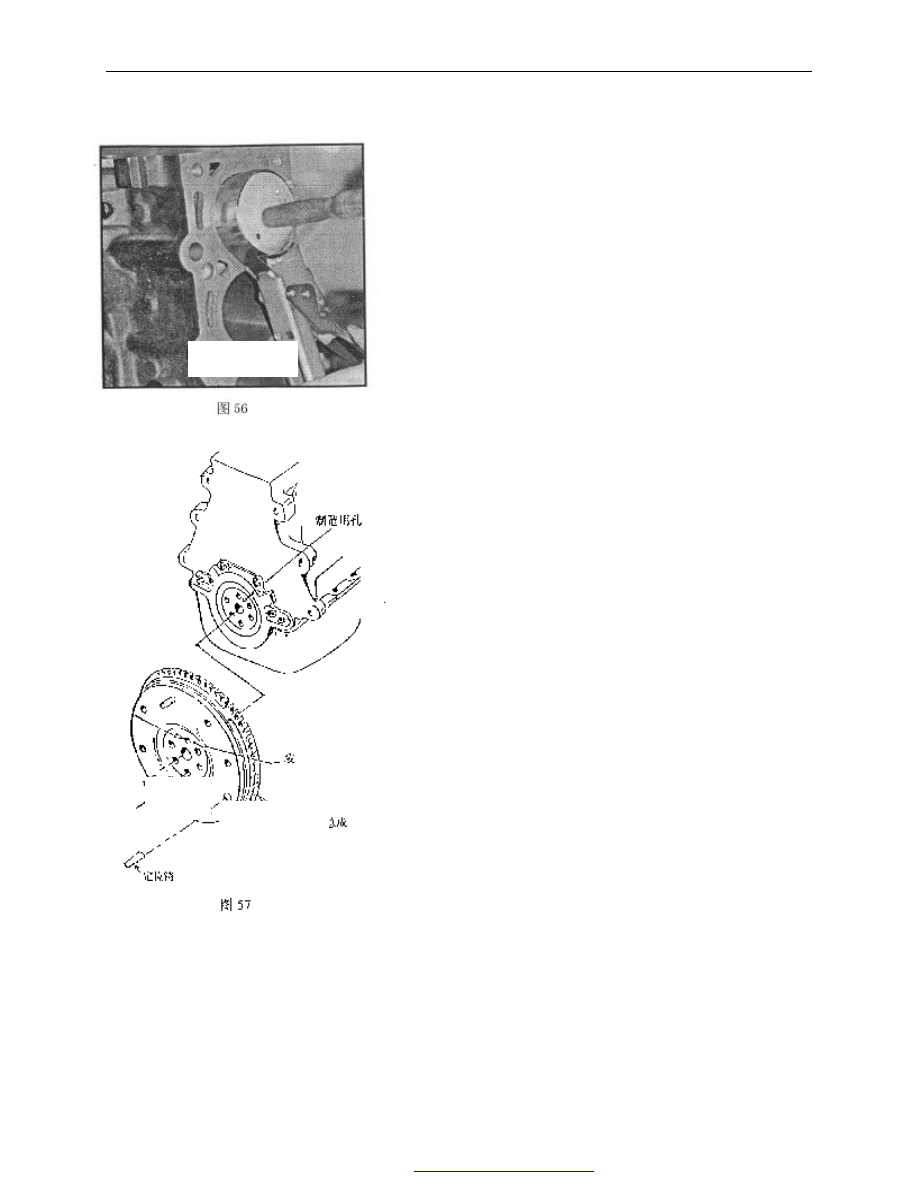
——During  assembling,  align  the  installation  mark  hole 
and  fabrication  hole  on  the  crankshaft.  Screw  in  6  new 
bolts  by  hand.  Bolts  should  have  sealant  on  them. 
Tightening torque is 82—92Nm. 

Fig.56   

Fig.57 

gage hole   

Install mark bore 

Flywheel 
assembly 

Retaining 
pin   

PDF 文件使用 "pdfFactory Pro" 试用版本创建  


www.fineprint.com.cn

CAC Gasoline Engine Maintenance And Servicing Manual 

39 

2). The removal and installation  of carrier assembly  of the real oil 
seal: 
Removal: 
——Remove 4 bolts (as arrow indicates). 
——Take out carrier assembly of the real oil seal   
——Remove carrier sealing gasket of the real oil seal 


——Use  chisel  or  screwdriver  to  pry  the  real  oil  seal  from  the 
carrier of the real seal oil. Note: please don’t damage the carrier of 
real oil seal. 


Installation: 
——Position the carrier on the  vise  which is  equipped  with wood 
on the jaw. 
——Align rear oil seal carrier hole with the part number side of oil 
seal outward .press oil seal into rear oil seal carrier with vise.. The 
magnitude  of  interference  for    real  oil  seal  and  carrier  hole  is 
0.26—0.50mm. 
——Install new sealing gasket of    real oil seal carrier . 
——Install real oil seal carrier assembly. Before assembling, wrap 
a piece of plastic piece on the crankshaft to avoid damaging oil seal. 
At the same time, apply engine oil on oil seal edge and journal for 
oil seal .   
——Measure the roughness of lower oil seal carrier surface and oil 
pan  flange surface  of  cylinder block.    It should be adjusted to the 
range of  ±0.26mm. 


Fig.58 

Fig.59 

Fig.60 

Fig.61 

PDF 文件使用 "pdfFactory Pro" 试用版本创建  


www.fineprint.com.cn

CAC Gasoline Engine Maintenance And Servicing Manual 

40 


——Tighten  four  M6  bolts  to 
8.0 —11.0Nm。 
——Remove the plastic piece. 


11】.  Removal  and  installation 

crankshaft, crankshaft thrust washer, halves and main bearing cap   

Removal: 
——Before removing, check the end play of crankshaft first. 
Use the plunger of dial indicator to contact bearing face of the crankshaft 
( lightly compressing). 

Push  the  crankshaft  away  from  the  contacting  tip.  Adjust  dial 

indicator  to  zero  and  then  use  post  to  push  the  crankshaft  towards 
contacting  tip  as  much  as  possible.  Check  dial  indicator.  The  reading  is 
end play. The end play of the crankshaft should be 0.092—0.303mm. 

If  dial  indicator  is  not  available,  the  end  play  of  the  crankshaft 

may be  checked by  feeler leaf. Between the  third  main bearing cap and 
crankshaft,  it  should  be  checked  by  feeler  leaf  (push  and  pull 
crankshaft)。 
——Loosen main bearing bolt and stud,(start with the middle bearing 
cap), take  out  the bolt and stud, remove  main bearing cap and the  other 
shell of main bearing bushings. The other shell of main bearing bushing 
is still kept in main bearing cap. 
——Remove the crankshaft. 
——Remove  the  thrust  plates  of  crankshaft  (two  pieces)  from  the 
cylinder block. 
Check: 
——Check main journal and main bearing bushing clearance . 

Clean  the  main  journal  of  crankshaft,  inner  bore  of  main  bearing 

cap and main bearing bushings with non-woven. Put plastic                             
clearance  gauge  on  the  main  journal  paralleling  with  the  generatrix  of 
main journal. Its length should be a little shorter than the width  of  main 
journal.   

Note: Don’t rotate the crankshaft! 

Mount  the  main  bearing  cap.  Screw  the  bolt  of  main  bearing  cap 

by hand. Tighten to 90—100Nm. Don't rotate the crankshaft.   


Remove  main  bearing  bolt.  Take  out  the  main  bearing  cap 

Fig. 62 
 

Fig.63 

Fig. 64 

Sealing plate 

M6 bolt×20(4) 
Tighten torque 8~11Nm 

Fig.62 

PDF 文件使用 "pdfFactory Pro" 试用版本创建  


www.fineprint.com.cn

CAC Gasoline Engine Maintenance And Servicing Manual 

41 

carefully. Arrange them according to the sequence. Read the bearing clearance 
according  to  the  proportion  stated  in  the  cover  of  plastic  clearance  gauge. 
Check the bearing  clearance from the third  main bearing and extending to the 
two sides. The clearance of main bearing is 0.011—0.058m m. 
——Check clearance of connecting rod bearing 

Use the above method to check clearance of connecting rod bearing. 

Clearance of connecting rod bearing is 0.006—0.06mm. 

——The size of connecting rod journal and connecting rod 
bushing:                                                                        unit:mm 
 

——The size of main journal and main bearing half: 

unit:mm 


Level 

The diameter of connecting 

rod journalφ 

The thickness of 

connecting rod 

bushing 

standard 

47.89—47.91 

1.480—1.487 

u

ndersize 0.025 

47.89—47.91 

1.492—1.499 

undersize 0.25 

47.64—47.66 

1.605—1.612 

undersize 0.5 

47.39—47.41 

1.730—1.737 

undersize 0.75 

47.14—47.16 

1.855—1.862 

undersize 1.0 

46.89—46.91 

1.980—1.987 

Level 

The diameter. 

of main 

journal 

The diameter of 

main bearing bore 

of cylinder body 

The thickness 

of main 

bearing half 

shell 

Standard 

57.98—58.00 

62.2935±0.0065 

2.131—2.138 

oversize 0.4 

57.98—58.00 

62.6935±0.0065 

2.331—2.338 

undersize 

0.002 

57.98—58.00 

62.2935±0.0065 

2.141—2.148 

undersize 0.25  57.73—57.75 

62.2935±0.0065 

2.256—2.263 

undersize 0.50  57.48—57.50 

62.2935±0.0065 

2.381—2.388 

undersize0.75 

57.23—57.25 

62.2935±0.0065 

2.506—2.513 

undersize 0.25 

oversize 0.4 

57.73—57.75 

62.6935±0.0065 

2.456—2.463 

undersize 0.50 

oversize 0.4 

57.48—57.50 

62.6935±0.0065 

2.581—2.588 

undersize 0.75 

oversize 0.4 

57.23—57.25 

62.6935±0.0065 

2.706—2.713 

Fig.65   

Fig. 66 
 

Fig. 67 

PDF 文件使用 "pdfFactory Pro" 试用版本创建  


www.fineprint.com.cn


Content   ..  28  29  30  31   ..