Chery QQ6 (S21) / S12LHD. Manual - part 60
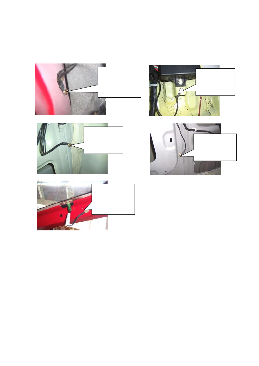
Grounding point of
interior
harness
under the left A
post.
BCM grounding
point at the side
of BCM
Grounding point of
defroster harness at the
top of back door.
Grounding point of
interior harness at
the left side of
luggage boot.
Grounding point of
interior harness at the
inside of rear right
fender.