Chery QQ6 (S21) / S12LHD. Manual - part 51


  Index      Chery     Chery QQ6 (S21) / S12LHD - service repair manual


Search            


Content   ..  49  50  51  52   ..


Chery QQ6 (S21) / S12LHD. Manual - part 51


30 

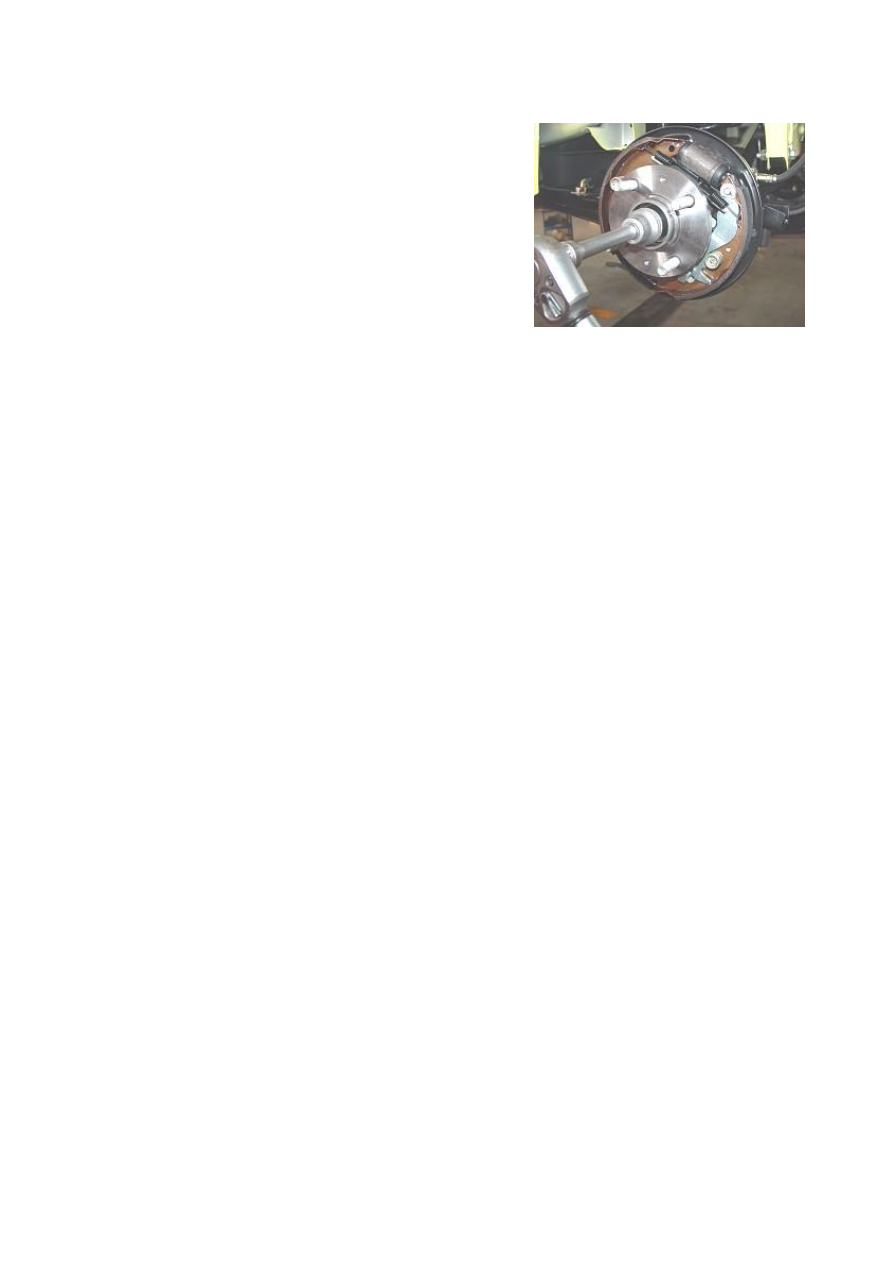
4.4.4 Remove the lock nuts from the rear brake with drum   

assywith a 30# combination sleeve, and then take off the rear   

brake with drum assy.   

Torque: 180±10N.m 


4.4.5 Remove the rear axle assy.   


5. Installation Step 

The installation step is reverse to that of removal. 


31 

III. Adjustment of Four-Wheel Alignment System 

Please  check  and  adjust  the  parameters  with  the  help  of  the  four-wheel  alignment  system 

recommended by the CHERY Automobile Co.. Ltd.   

S21 standard four-wheel alignment system parameters:   

Item 

Parameter 

Model 

SQR7130S21 

SQR7110S21 

Front Wheel 

Camber Angle 

0.87°±50′ 

0.87°±50′ 

Kingpin Caster 

Angle 

3.4°±30′ 

3.4°±30′ 

Kingpin 

Inclination Angle 

12.7° 

12.7° 

Front 

Wheel 

Front Wheel 

Toe-In 

6′±6′ 

6′±6′ 

Rear Wheel 

Camber Angle 

0°±30′ 

0°±30′ 

Rear 

Wheel 

Rear Wheel 

Toe-In 

0°±10′ 

0°±10′ 

Sideslip   

≤ 3m/km 

≤ 3m/km 


1. Adjustment of Front Wheel Toe-In 

The toe-in can be adjusted using an optical tester or a mechanical toe-in regulator.   
1.1  On  the  basis  of  requirement  of  the  tester,  position  the  wheels  and  conduct  the  preparation 
work before adjusting. 
1.2 Loosen the lock  nut and  of the  elastic  protective sleeve snap ring right steering tie bar. Turn 
the toe-in regulator lever as required to regulate the length until it reaches the specified value; and 
the toe-in value: 6′±6′. 
1.3  Tighten  the  lock  nut,  reinstall  the  elastic  snap  ring  of  protective  sleeve,  and  then  check 
whether the lock nut is tightened and whether the position of protective sleeve is proper;   
Torque: 35±3Nm 
1.4 After adjusting toe-in of front wheel, check whether the steering wheel is horizontal. 
Otherwise,  loosen  the  lock  nut  of  steering  wheel,  regulate  the  steering  wheel  to  the  horizontal 
position, and then tighten the steering wheel lock nut to the specified torque. 

2. Adjustment of Front Wheel Camber Angle 

2.1 In the normal case, after the independent suspension and   

wheel steering knuckle are assembled, it is unnecessary to   

adjust the camber angle. If the wheel camber angle is found   

deviated from the tolerance range due to the other causes,   

apply the connecting bolts of independent suspension and   

steering knuckle to correct the camber angle.:   

Front wheel camber angle: 0.87°±50′ 


32 

2.2  Before  correction,  check  (visually)  whether  the  parts  of  running  system  is  damaged,  and 

repalce the damaged parts;   


2.3 If the  front  wheel  camber angle is found  out  of the  tolerance range, loosen the connecting 

bolts of front shock absorber and steering knuckle, and move the wheel to correct the angle. 

3. Adjustment of Kingpin caster and inclination angles 

The  Kingpin  caster  and  inclination  angles  are  guaranteed  by  the  design  structure,  without 

adjustment in service. The Kingpin caster angle: 3.4°±30′, Kingpin inclination angle: 12.7°. If any 

parameter exceeds the specified range, replace thesteering knuckle only. 

4. Adjustment of rear wheel positional parameters 

All of the rear wheel alignment parameters shall be guaranteed through design process. 

4.1 Rear wheel camber angle: 0°±30′


4.2 Rear wheel toe-in: 0°±10′ 

4.3  If  the  rear  wheel  alignment  parameters  change  due  to  the  deformation  of  rear  axle  which  is 

subject  to  the  very  big  impact  force,  and  these  parameters  exceed  the  specified  range,  correct  or 

replace the rear axle only.   

IV. Installation of Tire and Regulation of Air Pressure 

1.    Assembly of Tire Valve   

Prior to the assembly of tire valve, firstly check the valve port to ensure whether it is smooth and 

free  from  burr,  and  then  apply  glycerol  on  the  rubber  body  surface,  or  soak  the  tire  valve  into 

glycerol. Pull or press using special tools with 200 - 400N to make the locating ring of the valve 

can go through the wheel  holes, to this  point, the assembly is completed (soap water is allowed 

to substitute glycerol). 

2. Assembly of Tire 

Before assembly of the tire, apply glycerol or soap water along the cycle of tire bead, meanwhile, 

note that: 

2.1 If the wheel rim has the dot marks, align the uniformity testing marks with the dot marks of 

the wheel rim.   

2.2 When without dot marks on the wheel rim, align the dynamic balance testing mark of tire to 

valve position. 

2.3 When without dot marks on the wheel rim, additionally, there is no dynamic balance testing 

mark,  however,  static  balance  testing  mark  is  available,  align  the  valve  to  the  static  balance 

testing mark. 

2.4 The description concerning the uniformity, dynamic balance and static balance testing marks 

33 

for tires will be additionally provided in written forms by product division of Chery Company or 

suppliers, and indicated on process sheet. 

2.5  Carry  out  tire  inflation  strictly  in  accordance  with  specified  pressure.  During  inflating 

process,  air  pressure  shall  not  exceed  10%  of  rated  pressure.  When  performing  separate 

packaging  to  spare  wheel  assembly,  the  rated  inflation  pressure  shall  be  3.0  bar,  and  the  spare 

wheel  assembly  shall  be  stored  separately  from  four  wheels.  Before  the  four-wheel  alignment 

work,  check  the  air  pressure  of  tires  of  four  wheels  and  regulate  the  pressure:  2.3  bar  for  front 

wheel, and 2.1bar for rear wheel.   

3. Tire Inflation 

After  completion  of  tire  inflation,  screw  up  the  protective  cap  of  valve,  and  then  carry  out 

dynamic  balancing  test.  Fit  appropriate  balance  weight  at  the  internal  and  external  fringe  of 

wheel rim as required.  It is required that the  unbalancedness of the final assembly shall be  less 

than  100  g·cm,  which  is  approximately  equivalent  to  a  5g  balance  weight  at  the  internal  and 

external  fringe of  wheel rim. Note: each  wheel and each side can use  only  one balance  weight. 

Additionally, its  maximum  mass shall not be  more than  70g. During assembling  process,  never 

hit  the  balance  weight  too  heavy.  Otherwise,  replace  balance  weight  in  time.  In  addition,  never 

use the replaced balance weight again. 

4. Installation of Wheel and Tire Assy 

When  install  wheel  and  tire  assy,  firstly,  manually  screw  up  the  wheel  bolt  onto  the  hub  for 

pretension, then use special tools for tightening in accordance with diagonal process. Tightening 

torque shall be 110±10N.m. It is prohibited to use impact wrench to cause wheel damage, over 

loose  or  over  tight.  It  is  not  allowed  to  apply  grease  on  wheel  bolt.  (For  the  newly-installed 

wheel and tire assy, after the initial mileage of 100 km, tighten the wheel bolts once to ensure the 

tightening torque. Checking the tightening torque of wheel bolts is one of routine maintenance.)   

5. Method to Tighten the Wheel Nut 

Tighten the fixing nut in a decussate way, the tightening force shall be approximately equal, then 

wheel shall be able to turn freely. When carry out final tightening, the wheel shall be on the 

ground. 

6. Installation of Trim Cover 

Install trim cover or place trim cover as required. When fitting clip- type trim cover, place knock 

in position by hand or via rubber tools. 


Content   ..  49  50  51  52   ..