Chery A18. Manual - part 47


  Index      Chery     Chery A18 - service repair manual


Search            


Content   ..  45  46  47  48   ..


Chery A18. Manual - part 47


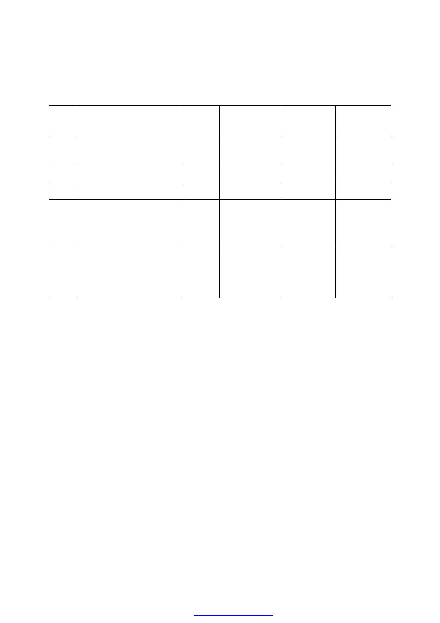
OIL PRESSURE TESTING PARAMETER LIST 


Serial 

No. 

Subject 

Rev 

r/min 

Pressure Kpa 

(Kgf/cm

2

Judgment 

Index 

Achievement 

Oil Yield Starting Time(s)


200 


Oil yield 

starting 

≤4 

Oil output(L/min) 

800 

196(2) 


>6 


Oil output(L/min) 

3000 

294(3) 


>28 

Opening Pressure of 

Pressure Limit Valve: Kpa 

(Kgf/cm

2

2000 


Oil yield 

starting 

440±20 

(4.49±

0.2) 

Seal 


686(7.0) 

No oil 

leakage on 

each faying 

face 

Passed 


Maintenance Manual of Karry 


(MK60 ABS) 


Service Department of Chery Automobile Distribution CO., Ltd 

Contents 


1. 

Flow chart of trouble diagnosis................................................................................................. 3 

2. 

Precautions for fault diagnosis .................................................................................................. 4 

3. 

Operational method and function introduction of fault-diagnosing device .............................. 4 

3.1


Operational method ............................................................................................................ 4


3.2


Introduction on function code ............................................................................................. 4


3.3


Functional key ................................................................................................................... 4


4. 

Servicing point of adventitious fault ......................................................................................... 5 

5. 

MK 60 ABS System.................................................................................................................. 6 

5.1


Inspection on ABS warning lamp........................................................................................ 6


5.2


Reading of state information............................................................................................... 6


5.3


Read fault code .................................................................................................................. 6


5.4


Eliminate fault code ........................................................................................................... 6


5.5


Display mode of fault code................................................................................................. 6


6. 

Diagnosis of hydraulic control unit........................................................................................... 7 

7. 

Indexed list for rapid trouble shooting ...................................................................................... 8 

7.1


Index for fault inspecting list of fault code .......................................................................... 8


7.2


Index for fault inspecting list of faultless code .................................................................... 8


8. 

ABS ECU Socket...................................................................................................................... 9 

9. 

Electric wiring diagram........................................................................................................... 10 

10.  Fault inspecting list of fault code ............................................................................................ 11 
11.  Fault inspecting list of faultless code ...................................................................................... 18 
12.  Inspection on ABS system ...................................................................................................... 24 
13.  Inspection on ABS operation .................................................................................................. 26 

13.1


Inspection on output voltage of speed sensor of wheel ...................................................... 26


13.2


Check hydraulic control unit (HCU) ................................................................................. 26


14.  Disassembly and assembly...................................................................................................... 27 

14.1


Precautions ...................................................................................................................... 27


14.2


Disassembly of MK60 HECU assembly ........................................................................... 27


14.3


Reinstallation of ABS assembly........................................................................................ 28


15.  ECU coding............................................................................................................................. 29 
16.  Liquid adding and exhaust ...................................................................................................... 30 

16.1


Wet-type HECU ............................................................................................................... 30


16.2


Dry-type HECU ............................................................................................................... 30


1.  Flow chart of trouble diagnosis 


Content   ..  45  46  47  48   ..