Chery A18. Manual - part 21


  Index      Chery     Chery A18 - service repair manual


Search            


Content   ..  19  20  21  22   ..


Chery A18. Manual - part 21


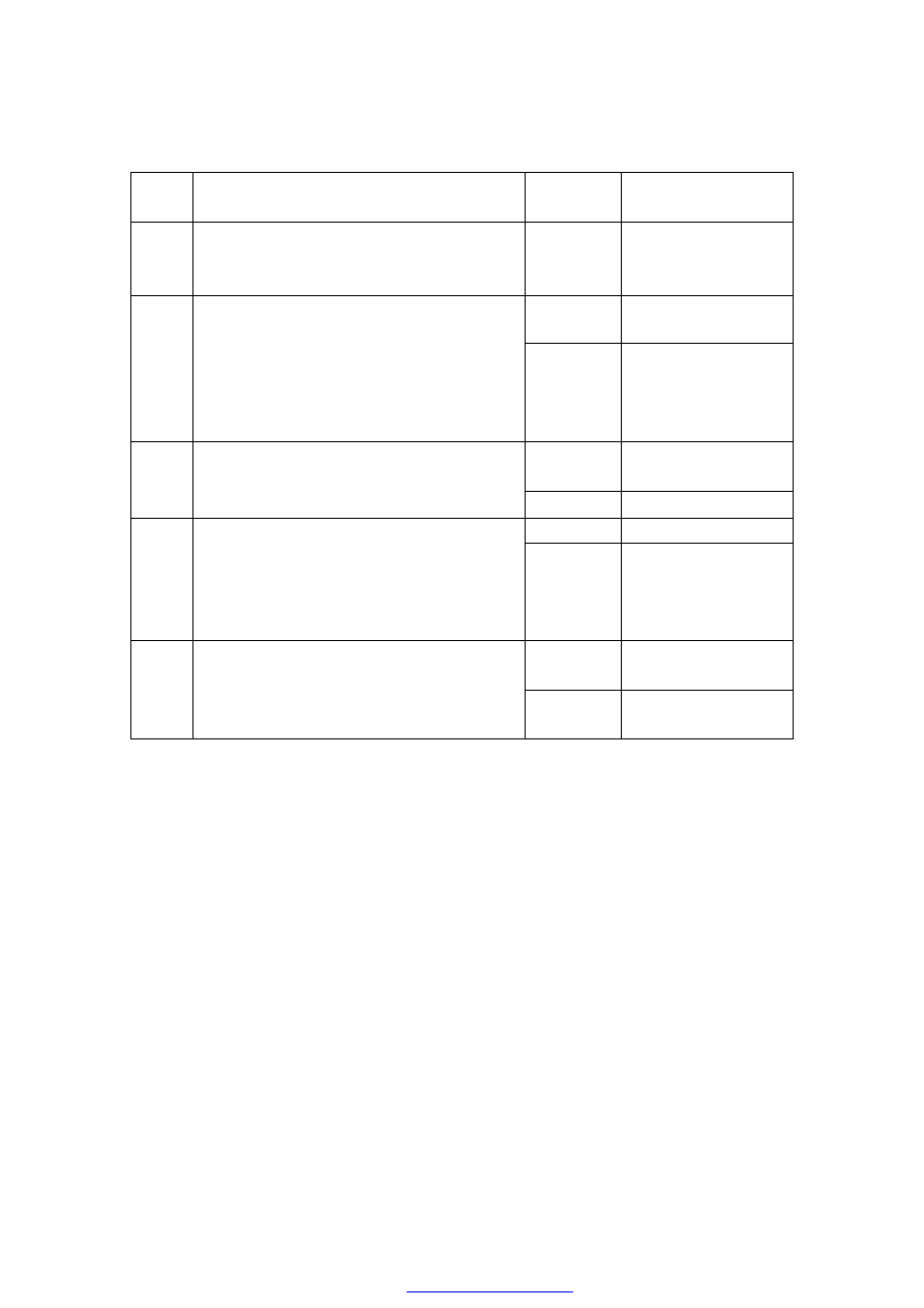
Diagnostic  trouble  code:  P0647  “Overvoltage  in  control  circuit  of  A/C 
compressor relay” 

Item 

No. 

Operation procedure 

Inspection 

results 

Follow-up 

procedure 

Connect the  diagnostic  tester and  adaptor 
and  turn  the  ignition  switch  to  “OFF” 
position. 


Proceed to next step 

Yes 

Proceed to Step 4 

Pull  out  the  A/C  relay,  turn  the  ignition 
switch  to  “ON”  position  and  check  if the 
voltage  between  the  power  supply 
terminal of relay (i.e. 30# and 85# pins of 
the  relay)  and  the  negative grid of power 
supply is about 12V. 

No 

Proceed to next 

step. 

Yes 

Repair or replace 

the wiring harness 

Check if the power supply circuit of relay 
is open or short to ground. 

No 

Proceed to Step 2 

Yes 

Replace the relay 

Inspect  with  multimeter  to  check  if  the 
voltage  between  the  control  terminal  of 
A/C  compressor  relay  (i.e. 86# pin of  the 
relay)  and  the  negative  grid  of  power 
supply is about 3.7V. 

No 

Proceed to next step 

Yes 

Repair or replace 

the wiring harness 

Check  if  the  circuit  between  the  control 
terminal  of  A/C  compressor  relay  (i.e. 
86# pin of the relay) and 70# pin of ECU 
is short to supply. 

No 

Refer to diagnosis 

help 


Diagnostic trouble code: P1651 “Malfunction in control circuit of malfunction 

alarm light” 

Item 

No. 

Operation procedure 

Inspection 

results 

Follow-up procedure 

Connect  diagnostic  tester  and  adaptor, 
and  turn  the  ignition  switch  to  “ON” 
position. 


Proceed to next step 

Yes 

Proceed to next step 

Check the action of engine malfunction 
alarm  light  by  using  the  “actuator 
action  testing"  function  of  diagnostic 
tester  and  observe  whether  the  light  is 
always on or off. 

No 

Normal operation 

Yes 

Repair or replace the 

wiring harness. 

Verify  that  the  supply  circuit  of  engine 
malfunction alarm light is open or short 
to ground. 

No 

Proceed to next step 

Yes 

Repair or replace the 

wiring harness. 

Check  if the supply circuit between the 
control 

terminal 

pin 

of 

engine 

malfunction  alarm  light  and  29# pin  of 
ECU  is  open,  or  is  short  to  ground  or 
power supply. 

No 

Refer to diagnosis 

help. 


PROCEDURES FOR FAULT DIAGNOSIS ACCORDING TO THE 

SYMPTOMS OF THE ENGINE 

A preliminary inspection should be carried out before implementing the steps of fault 
diagnosis according to the symptoms of engine: 

(1) Verify that there is no abnormal behavior with the ECU and malfunction indicator 

light (not applicable for car models without setting of malfunction indicator light). 

(2)  Inspect  with  the  diagnostic  tester  or  flashing  light  to  verify  that  there  is  no 

malfunction information record. 

(3) Inspect  the  idle  speed  data of warmed  up  engine  in the electronic  control  system 

with the diagnostic tester and verify that they are normal. 

(4)  Verify  that  the  malfunction  symptom  complained  by  the  car  owner  exists  and 

locate the exact position of the symptom. 

Then  carry  out  the  visual  inspection:  Verify  that  the  grounding  point  of  the  wiring 
harness is clean and firm. 

Verify that the vacuum pipelines have any ruptures or twists together, and whether its 
connections are correct. 

Verify that the pipeline has any symptom of blockage. 

Verify that the air inlet pipeline is flattened or damaged. 

Verify  that  the  sealing  between  the  throttle  body  and  the  air  intake  manifold  is  in  a 
good condition. 

Verify  that  the  high  voltage  cable  of  ignition  system  has  any  rupture  or  ageing,  and 
whether the wire routing is correct. 

Verify that the connection of conducting wire is correct and whether the connector is 
loose or poorly contacted. 


1) The engine is not running or running slowly during starting 

Item 

Operation procedure 

Inspection 

results 

Follow-up procedure 

Yes 

Proceed to next step 

Inspect with multimeter to see whether there 
is a voltage of about 10-12.5V between two 
battery terminals. 

No 

Repair or replace the 

battery 

Yes 

Proceed to next step. 

Turn  the  ignition  switch  to  “ON”  position. 
Inspect with multimeter to see whether there 
is  a  voltage  of  about  10-12.5V  between the 
terminals connecting the ignition switch and 
the positive grid of the battery. 

No 

Repair the terminal 

or replace the 

conducting wire 

Yes 

Proceed to next step. 

Keep  the  ignition  switch  at  the  startup 
position  and  inspect  with  multimeter  to  see 
whether that there is a  voltage of more than 
8V  between  the  terminals  connecting  the 
ignition  switch  and  the  starting  motor 
magnetic clutch. 

No 

Repair or replace the 

ignition switch 

Yes 

Repair or replace the 

starting motor 

Inspect  with  multimeter  to  see  whether  the 
starting motor has any open or short-circuit. 

No 

Proceed to next step. 

Yes 

Fix the malfunction 

Verify  that  the  engine  is  jammed  due  to 
poor lubricating. 

No 

Proceed to next step. 

Yes 

Replace with 

appropriate 

lubricating oil 

In  case  of  winter  season,  inspect  to  see 
whether  there  is  too  much  friction  in  the 
starting motor due to the improper selection 
of engine lubricating oil and gearbox oil. 

No 

Inspect other items 


Content   ..  19  20  21  22   ..