Loader Bobcat 773. Manual - part 118
C
P–17333
1
1
3
2
A
P–16578
1
B
P–13732
P–13725
1
1
–10–36–
Service Manual
773 BICS Loader
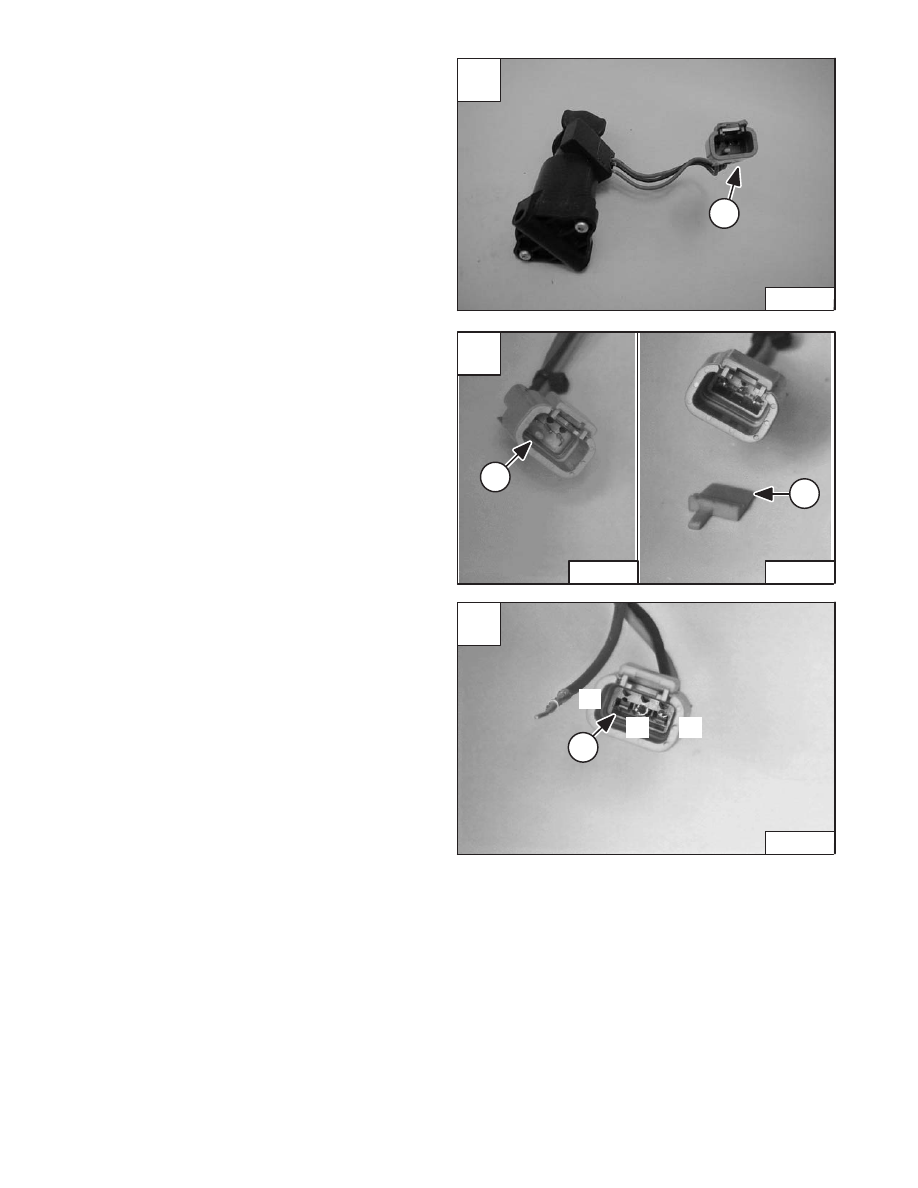
CONTROL HANDLE
(ADVANCED HAND CONTROL)
(AHC) W/PUSH BUTTON FLOAT (Cont’d)
Handle Sensor Connector
The wire connector (Item 1) [A] can be removed from the
handle sensor wires, use the following procedure.
Remove the wedge (Item 1) [B] from the connector.
With a pointed tool, lift the tab (Item 1) [C] and pull the wire
from the connector.
Assembly: Install the wires into the connector as listed
below [C]:
1–Terminal – Red
2–Terminal – Black
3–Terminal – Green
Revised June 01