Loader Bobcat 773. Manual - part 91


  Index      Bobcat     Bobcat 773 - service manual 1997 year


Search            


Content   ..  89  90  91  92   ..


Loader Bobcat 773. Manual - part 91


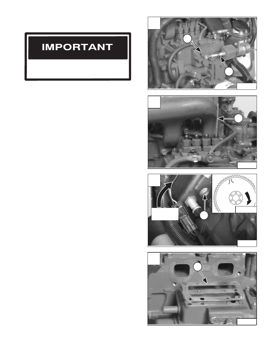
Rotate slowly until fuel just starts to flow upward into the
plastic tube.

At this instant, the 22.5

°

 or 19

°

 BTDC timing mark on the

flywheel should be aligned with the mark in the window
(Item 1) [C].

Add or subtract shim(s) (Item 1) [D] as needed to adjust
the fuel delivery timing.

FUEL INJECTION PUMP (Cont’d)

Timing The Injection Pump

Do not attempt to maintain or adjust unless
you are trained and have the correct
equipment.

I–2028–0289

Timing the injection pump is done by changing the
number of shims between the injection pump and the
injection pump mounting surface.

Disconnect the number one cylinder high pressure line
from the injection pump.

Disconnect the fuel shut–off linkage (Item 1) [A] from the
injection pump.

Turn the fuel supply lever (Item 2) [A] to the ON position
(to the right).

Install a short plastic tube (Item 1) [B] in the number one
cylinder port of the injection pump. The tube should fit
securely in the port and point upward.

Rotate the engine in the direction shown [C].

Continue rotation until flywheel timing mark just appears
in the window (Item 1) [C].

NOTE: Adding or removing one shim will vary the

timing by 1.5

°

. Adding shims retards timing.

NOTE: The flywheel has two timing marks. The first

mark to appear in the window with the
rotation shown is 22.5

°

. The first mark is used

for 773 loaders. The second mark to appear
in the window is 19

°

 which is used for 753

loaders.

A

P–04306

1

2

C

P–04315

1

Rotation

Direction

MC–01542

19

°

22.5

°

Rotation

D

P–04364

1

773 BICS Loader

–7–43–

Service Manual

B

P–04361

1

FUEL INJECTION NOZZLES

Removal And Installation

The following are some problems caused by faulty
injectors:

– Engine is hard to start or will not start
– Rough engine operation and idle
– Engine will not have full power
– Excessive exhaust smoke

Do not bend the high pressure fuel injection
tubes when removing or installing them.

I–2029–0289

Disconnect the fuel return hoses (Item 1) [A] & [B] from
the injectors.

Disconnect the high pressure fuel lines (Item 1) [C] from
the fuel injectors and from the injection pump.

Remove the high pressure fuel lines from the engine.

Remove the retainer nut from the top of the fuel injectors
(Item 1) [D].

Remove the fuel return tube (Item 2) [D] from the fuel
injectors.

Diesel fuel or hydraulic fluid under pressure
can penetrate skin or eyes, causing serious
injury or death. Fluid leaks under pressure may
not be visible. Use a piece of cardboard or wood
to find leaks. Do not use your bare hand. Wear
safety goggles. If fluid enters skin or eyes, get
immediate medical attention from a physician
familiar with this injury.

W–2072–0496

A

P–04311

1

C

P–04330

1

D

P–04353

1

2

–7–44–

773 BICS Loader

Service Manual

B

P–04318

1

FUEL INJECTOR NOZZLES (Cont’d)

Removal And Installation (Cont’d)

Remove the injector nozzle (Item 1) [A] from the cylinder
head.

Photo  [B] shows the injector nozzle removed from the
cylinder. Inspect the injector and replace if necessary.

Installation:  be sure the nozzle cap (Item 1) [B] and
copper washer (Item 2) [B] are in the correct position.
Replace the nozzle cap and copper washer when
installing new or used injectors.

A

P–04354

1

773 BICS Loader

–7–45–

Service Manual

B

P–04358

1

2

FUEL INJECTOR NOZZLE (Cont’d)

Checking The Injector Nozzle

Do not disassemble or test the fuel injector
nozzles unless you have the correct service
and testing tools.

I–2027–0284

The tool listed will be needed to do the following
procedure:

OEM1064 – Injector Nozzle Tester

Disassemble and clean the injector nozzle.

The nozzle release pressure can be adjusted by adding
or removing spacer(s) (Item 2) [A] from the top of the
nozzle spring (Item 3) [A].

Each spacer will change the release pressure by about
142 PSI (980 kPa).

Fuel Injection Pressure

1991–2133 PSI

. . . . . . . . . . . . . . 

(13728–14707 kPa)

Assemble the injector nozzle. Connect the nozzle to the
tester with the nozzle down [B].

Operate the hand lever at a slow rate and record the
opening pressure. If the pressure is not correct,
disassemble the nozzle and add or remove spacers (Item
2) [A] as needed.

When the injector nozzle is assembled, tighten the nozzle
body to 43–58 ft.–lbs. (59–79 Nm) torque.

Check for inside leakage. Operate the hand lever until the
pressure is 1850 PSI (12755 kPa). Keep the nozzle under
this pressure for 10 seconds, check to see if fuel leaks
from the nozzle. If fuel leaks, replace the nozzle.

Check that the spray pattern is correct [C]:

1. Fuel does not come out the side of the nozzle.

2. Drops of fuel are not present at the nozzle.

3. The injector has an even flow coming from the

nozzle.

B

A–02513

C

A–02621

CORRECT WRONG

A

PI–09981

1

2

3

4

5

6

7

(1) Nozzle Holder
(2) Adjusting Washer
(3) Nozzle Spring
(4) Push Rod
(5) Distance Piece
(6) Nozzle Piece
(7) Nozzle Retaining Nut

–7–46–

773 BICS Loader

Service Manual


Content   ..  89  90  91  92   ..