Loader Bobcat 773. Manual - part 64


  Index      Bobcat     Bobcat 773 - service manual 1997 year


Search            


Content   ..  62  63  64  65   ..


Loader Bobcat 773. Manual - part 64


LIFT ARMS

Removal And Installation

Roll the Bob–Tach fully forward. Stop the engine.

Move the hydraulic controls to release the hydraulic
pressure.

Remove the Bob–Tach frame from the lift arms. (See
Page 5–16.)

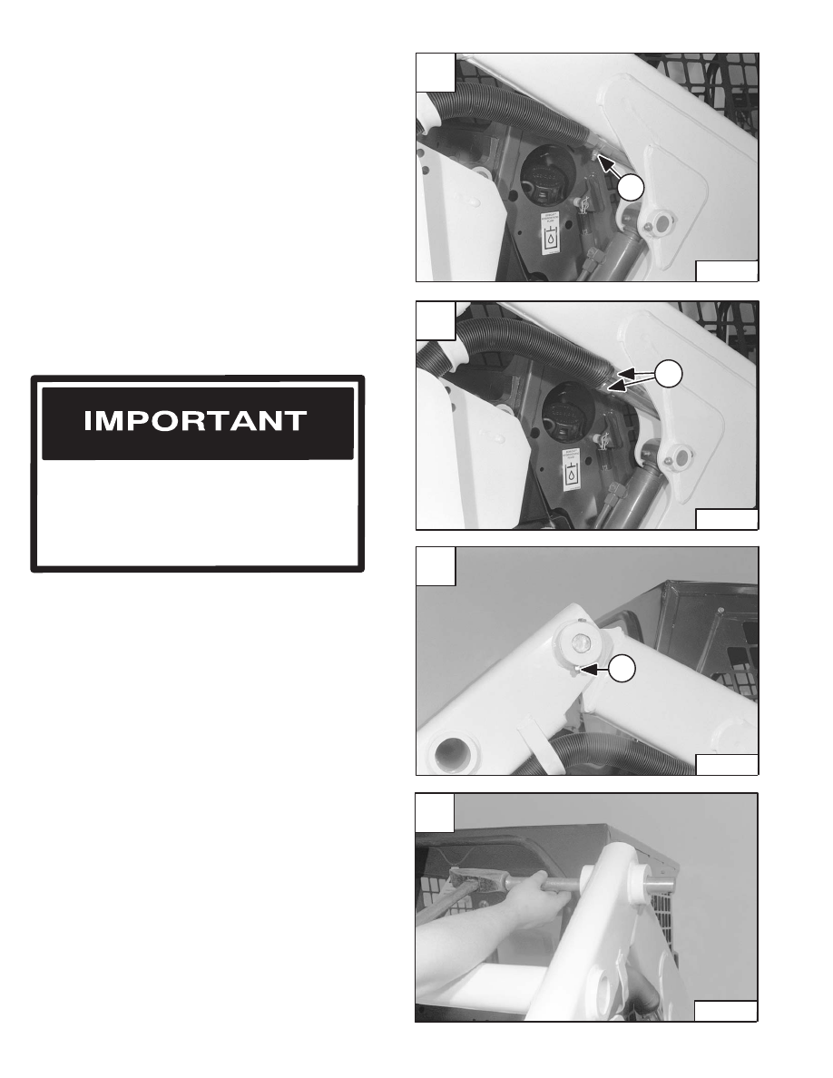
Remove the tubeline clamp (Item 1) [A] under the lift arm
for clearance (both sides).

Disconnect the hoses (Item 1) [B] (both sides).

Install plugs into the hose ends.

NOTE: Grease fittings on the pivot pins should be

removed before removing the pivot pins with
a punch and hammer.

Use a drift punch and hammer, remove the lift arm pivot
pin (both sides) [D].

Remove the retainer bolt and nut (Item 1) [C] from the lift
arm pivot pin (both sides).

Installation: Tighten the retainer bolt and nut to 18–20
ft.–lbs. (24–27 Nm) torque.

When repairing hydrostatic and hydraulic
systems, clean the work area before
disassembly and keep all parts clean. Always
use caps and plugs on hoses, tubelines and
ports to keep dirt out. Dirt can quickly damage
the system.

I–2003–0888

Revised Jan. 99

A

N–00829

1

C

N–00811

1

D

N–00814

–5–20–

773 BICS Loader

Service Manual

B

N–00830

1

LIFT ARMS (Cont’d)

Removal And Installation (Cont’d)

Remove the retainer bolt and nut from the lift cylinder rod
end pivot pin (Item 1) [A] (both sides).

Installation: Tighten the retainer bolt and nut to 18–20
ft.–lbs. (24–27 Nm) torque.

Raise the operator cab. (See Page 1–1.)

Remove the grease fitting (Item 2) [A] (both sides).

Installation: Reinstall the grease fitting (Item 2) [A] when
lift arms are reinstalled (Both sides).

Connect a nylon lift strap, chain and chain hoist to the lift
arms. (See Figure [C] for reference.)

Use a drift punch and hammer, remove the lift cylinder rod
end pivot pin (Item 1) [A] (both sides).

Remove the retainer bolt and nut (Item 1) [B] from the
stabilizer pivot pin (both sides).

Installation: Tighten the retainer bolt and nut to 18–20
ft.–lbs. (24–27 Nm) torque.

Use a drift punch and hammer, remove the stabilizer pivot
pin (Item 1) [B] (both sides).

Lift the lift arms with the chain hoist and move them away
from the loader [C].

Reverse the removal procedure to install the lift arms on
the loader.

Revised Jan. 99

A

N–00812

2

1

C

N–00815

773 BICS Loader

–5–21–

Service Manual

B

N–00813

1

LIFT ARM LINK

Removal And Installation

Lower the lift arms. Stop the engine.

Disconnect the tilt cylinder hoses between the lift arm link
and the lift arms.

Remove the retainer bolt and nut from the lift arm pivot pin
(Item 1) (both sides) [A].

Installation: Tighten the retainer bolt and nut to 18–20
ft.–lbs.(24–27 Nm) torque.

Use a drift pin and hammer, remove the lift arm pivot pin
[B] (both sides).

When repairing hydrostatic and hydraulic
systems, clean the work area before
disassembly and keep all parts clean. Always
use caps and plugs on hoses, tubelines and
ports to keep dirt out. Dirt can quickly damage
the system.

I–2003–0888

Connect a chain and chain hoist on the lift arm link [C].

Remove the retainer bolt and nut from the lift arm link
pivot pin (Item 1) [D] (both sides).

Installation: Tighten the retainer bolt and nut to 18–20
ft.–lbs. (24–27 Nm) torque.

Wear safety glasses to prevent eye injury when
any of the following conditions exist:

W–2019–1285

When fluids are under pressure.

Flying debris or loose material is present.

Engine is running.

Tools are being used.

Revised Jan. 99

A

N–00811

1

C

N–00816

D

N–00817

1

–5–22–

773 BICS Loader

Service Manual

B

N–00814

LIFT ARM LINK (Cont’d)

Removal And Installation (Cont’d)

Use a drift punch and hammer, remove the lift arm link
pivot pin (both sides) [A].

Raise the lift arm link with the chain hoist and remove it
from the loader frame.

Reverse the removal procedure to install the lift arm link
on the loader.

Revised Jan. 99

A

N–00818

773 BICS Loader

–5–23–

Service Manual


Content   ..  62  63  64  65   ..