Acura RSX Honda Integra. Manual - part 486


  Index      Acura     Acura RSX Honda Integra - service repair manual 2002-2006 year


Search            


Content   ..  484  485  486  487   ..


Acura RSX Honda Integra. Manual - part 486


04

05

YES

NO

23-76

SRS

DTC Troubleshooting (cont’d)

A

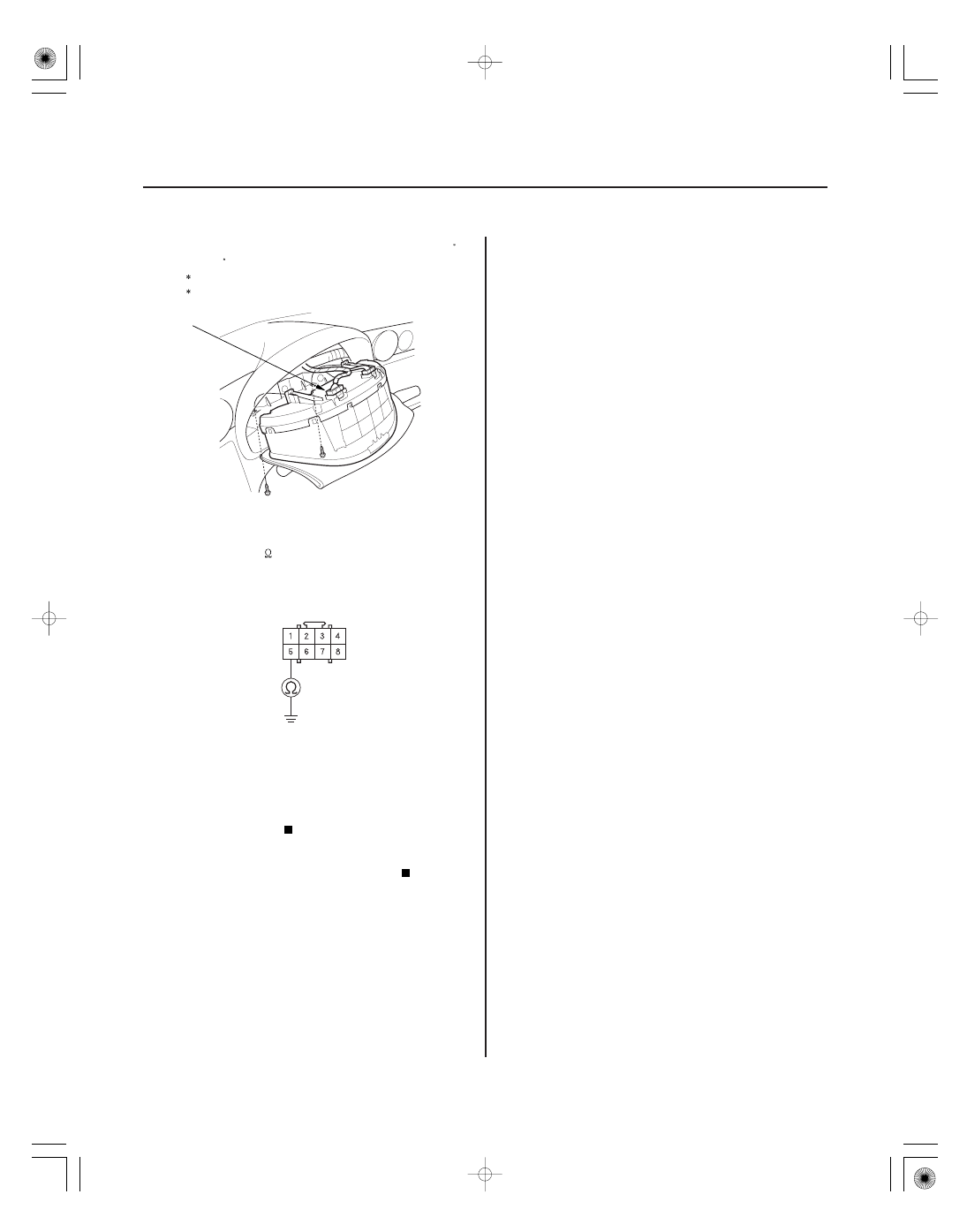
SRS UNIT CONNECTOR C (8P)

PNK

5. Reconnect the gauge assembly connector A (22P )

or (20P ) to the gauge assembly.

1: ’02-04 models
2: ’05-06 models

6. Check resistance between the No. 5 terminal of

SRS unit connector C (8P) and body ground. There
should be 500

or more.

Faulty SRS unit; replace the SRS unit

(see page 23-141).

Faulty SRS indicator circuit in the gauge

assembly; replace the gauge assembly.

1

2

Wire side of female terminals

Is the r esistance as specif ied?

05/06/27 18:09:54 61S6M040_230_0076

*02

02

S6M6A00K79100081092FAAT00

DTC 9-2:

YES

NO

YES

NO

YES

NO

23-77

A

SRS UNIT CONNECTOR A (18P)

Faulty Power Supply (VB line)

1. Check the No. 13 (10 A) fuse in the under-dash

fuse/relay box.

Go to step 5.

Go to step 2.

2. Replace the No. 13 (10 A) fuse.

3. Turn the ignition switch ON (II), and wait for

30 seconds. Then turn the ignition switch OFF.

4. Check the No. 13 (10 A) fuse.

The system is OK at this time.

Short in the under-dash fuse/relay box No. 13

(10 A) fuse circuit.

5. Disconnect the battery negative cable, and wait for

3 minutes.

6. Disconnect the driver’s airbag 4P connector

(see page 23-18).

7. Disconnect the front passenger’s airbag 4P

connector (see page 23-18).

8. Disconnect both seat belt tensioner 2P connectors

(see page 23-19).

9. Disconnect SRS unit connector A (18P) from the

SRS unit.

10. Reconnect the battery negative cable.

11. Connect a voltmeter between the No. 3 terminal of

SRS unit connector A (18P) and body ground. Turn
the ignition switch ON (II), and measure the voltage.
There should be battery voltage.

Faulty SRS unit or poor connection at the

SRS unit connector A (18P); check the connection. If
the connection is OK, replace the SRS unit
(see page 23-141).

Go to step 12.

12. Turn the ignition switch OFF.

13. Disconnect the battery negative cable, and wait for

3 minutes.

14. Disconnect dashboard wire harness B connector S

from the under-dash fuse/relay box (see page
22-55).

(cont’d)

Wire side of female terminals

Is the f use OK ?

Is the f use OK ?

Is ther e batter y voltage?

05/06/27 18:09:55 61S6M040_230_0077

*01

YES

NO

23-78

SRS

DTC Troubleshooting (cont’d)

SRS UNIT CONNECTOR A (18P)

DASHBOARD WIRE HARNESS B CONNECTOR S

15. Check resistance between the No. 3 terminal of

SRS unit connector A (18P) and the No. 2 terminal
of dashboard wire harness B connector S. There
should be 0

1.0

.

Open in the under-dash fuse/relay box or

poor connection at the dashboard wire harness
connector S; check the connection. If the
connection is OK, replace the under-dash fuse/relay
box (see page 22-60).

Open in dashboard wire harness B; replace

dashboard wire harness B.

Wire side of female terminals

Wire side of
female terminals

Is the r esistance as specif ied?

05/06/27 18:09:55 61S6M040_230_0078

S6M6A00K79100081131FAAT00

S6M6A00K79100081141FAAT00

DTC 13-1, 13-2:

DTC 14-1, 14-2:

YES

NO

YES

NO

23-79

23-79

Internal Failure of the Driver’s

Side Impact Sensor

Internal Failure of the Front

Passenger’s Side Impact Sensor

1. Erase the DTC memory (see page 23-23).

2. Turn the ignition switch ON (II), and check that the

SRS indicator comes on for about 6 seconds and
then goes off.

Replace the driver’s side impact sensor

(see page 23-142).

Intermittent failure, system is OK at this time.

Go to Troubleshooting Intermittent Failures
(see page 23-24). If another DTC is indicated, go to
the DTC Troubleshooting Index.

1. Erase the DTC memory (see page 23-23).

2. Turn the ignition switch ON (II), and check that the

SRS indicator comes on for about 6 seconds and
then goes off.

Replace the front passenger’s side impact

sensor (see page 23-142).

Intermittent failure, system is OK at this time.

Go to Troubleshooting Intermittent Failures
(see page 23-24). If another DTC is indicated, go to
the DTC Troubleshooting Index.

Does the SRS indicator stay on, and is DT C 13-1
or 13-2 indicated?

Does the SRS indicator stay on, and is DT C 14-1
or 14-2 indicated?

05/06/27 18:09:55 61S6M040_230_0079


Content   ..  484  485  486  487   ..