Acura RSX Honda Integra. Manual - part 440


  Index      Acura     Acura RSX Honda Integra - service repair manual 2002-2006 year


Search            


Content   ..  438  439  440  441   ..


Acura RSX Honda Integra. Manual - part 440


01

02

S6M6A00J32173631001FEAT00

22-99

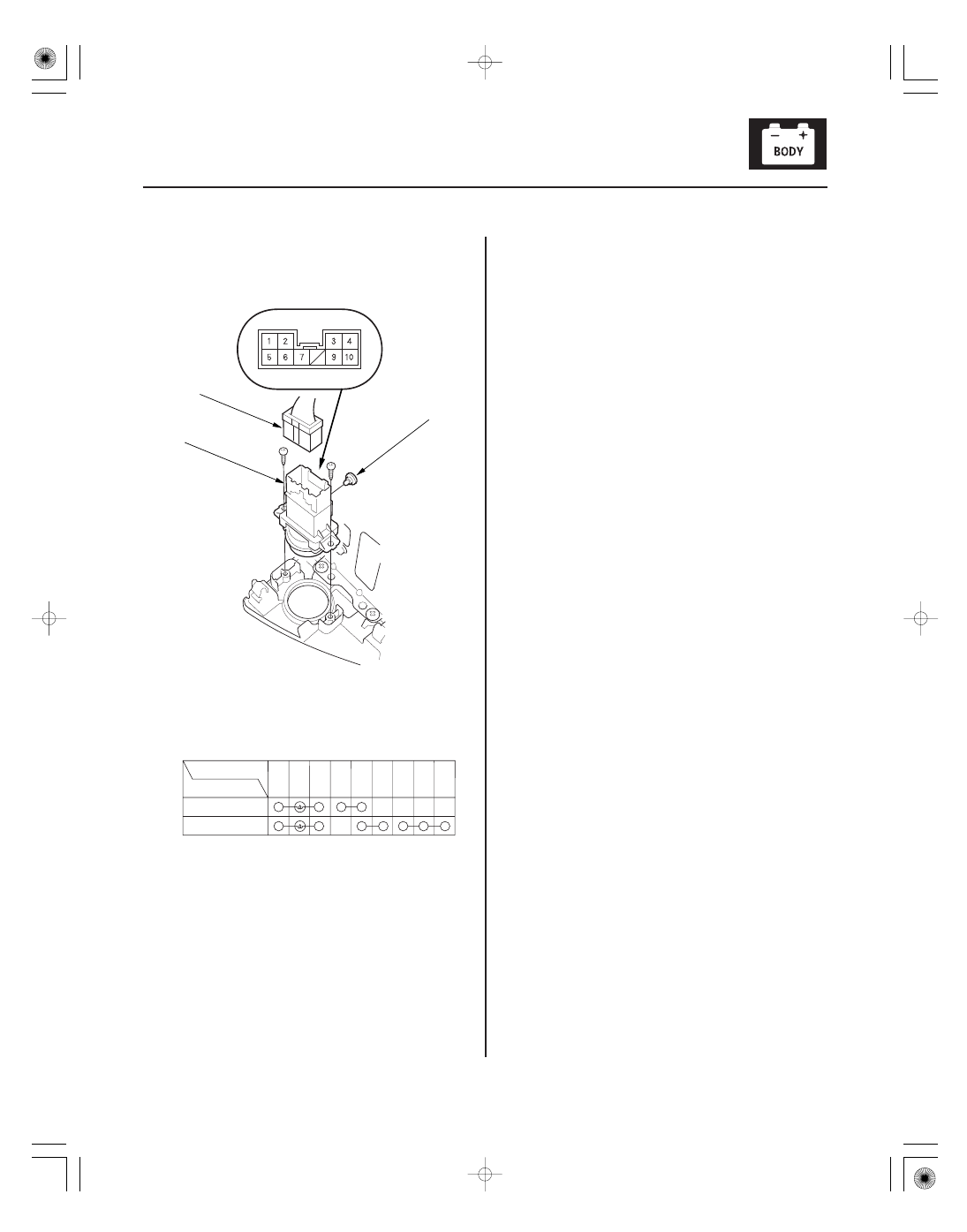
Hazard Warning Switch Test

C

A

B

Terminal

Position

ON

OFF

5

6

1

2

3

4

7

10

1. Remove the audio unit (see page 22-118).

2. Disconnect the 10P connector (A) from the hazard

warning switch (B).

3. Remove the two screws and the hazard warning

switch.

4. Check for continuity between the terminals in each

switch position according to the table.

5. If the continuity is not as specified, replace the

illumination bulb (C) or the switch.

05/06/27 18:04:00 61S6M040_220_0100

*01

S6M6A00J32323300000DAAT00

22-100

Entry Lights Control System

Component Location Index

PASSENGER’S DOOR SWITCH

CEILING LIGHT

IGNITION KEY LIGHT

IGNITION KEY SWITCH

DRIVER’S DOOR SWITCH

KEYLESS RECEIVER UNIT

DRIVER’S DOOR LOCK
KNOB SWITCH

UNDER-DASH
FUSE/RELAY BOX

CARGO AREA LIGHT

HATCH LATCH SWITCH

ENTRY LIGHT TIMER CIRCUIT
(In the multiplex control unit)

Test, page 22-107
Replacement, page 22-107

Test, page 22-104

Test, page 22-104

Input Test, page 22-169

Test, page 22-170

Test, page 22-108
Replacement, page 22-108

Test, page 22-108
Replacement, page 20-122

Input Test, page 22-102

05/06/27 18:04:02 61S6M040_220_0101

*01

S6M6A00J32323300000EAAT00

22-101

Circuit Diagram

BLU/BLK*

RED*

K10

WHT/GRN

RED

5

6

No. 3 (7.5 A)

No. 20*

UNDER-DASH FUSE/RELAY BOX

WHT/BLU

WHT/BLU

2

WHT/BLK

GRN/RED

BLU/ORN

K2

WHT

BAT

IG1

BLK/YEL

No. 10
(7.5 A)

O7

RED

RED

BLK

G401

X5

1

2

RED/WHT

LT GRN/RED

Q4

UN-
LOCK

G401

BLK

LOCK

YEL/RED

Y8

1

3

GRN

Q3

RED/BLU

X8

P18

G702*
G701*

BLK

MULTIPLEX CONTROL UNIT

BATTERY

No. 19 (100 A)

UNDER-HOOD FUSE/RELAY BOX

WHT/BLU

IGNITION
SWITCH

IG1 HOT in ON (II)
and START (III)

KEYLESS
RECEIVER
UNIT

UNDER-DASH
FUSE/RELAY
BOX

CEILING
LIGHT

IGNITION
KEY
LIGHT
(LED)

CARGO
AREA
LIGHT

SECURITY
CONTROL
UNIT

DOOR
LOCK KNOB

GAUGE
ASSEMBLY
(Beeper)

DRIVER’S
DOOR
LOCK
KNOB
SWITCH

DRIVER’S
DOOR
SWITCH
(Closed:
Door open)

PASSENGER’S
DOOR
SWITCH
(Closed:
Door open)

IGNITION
KEY
SWITCH
(Closed:
Key inserted)

HATCH
LATCH
SWITCH
(Closed:
Hatch open)

(Fuse/relay
box socket)

BLK

G701

1

2

: Shielding

No. 20 (40 A) :USA
No. 20 (50 A):Canada

*2: ’02-04 models
*3: ’05-06 models

*1

2

3

1

2

3

TRANSMITTER

KEY

05/06/27 18:04:03 61S6M040_220_0102

01

S6M6A00J32323341901FCAT00

22-102

Entry Lights Control System

Control Unit Input Test

UNDER-DASH FUSE/RELAY BOX CONNECTOR K (17P)

UNDER-DASH FUSE/RELAY BOX CONNECTOR O (12P)

UNDER-DASH FUSE/RELAY BOX CONNECTOR P (18P)

UNDER-DASH FUSE/RELAY BOX CONNECTOR Q (8P)

UNDER-DASH FUSE/RELAY BOX CONNECTOR X (8P)

UNDER-DASH FUSE/RELAY BOX CONNECTOR Y (13P)

BLU/ORN

GRN/RED

RED

GRN

LT GRN/RED

RED/WHT

WHT/BLK

YEL/RED

1. Before testing, troubleshoot the multiplex control system (see page 22-189).

2. Remove the driver’s dashboard lower cover (see page 20-63).

3. Disconnect the under-dash fuse/relay box connectors.

NOTE: All connectors are wire side of female terminals.

4. Inspect the connector and socket terminals to be sure. They are all making good contact.

• If the terminals are bent, loose or corroded, repair them as necessary, and recheck the system.
• If the terminals look OK, go to step 5.

05/06/27 18:04:03 61S6M040_220_0103


Content   ..  438  439  440  441   ..