Acura RL. Manual - part 434


  Index      Acura     Acura RL - service repair manual 2005-2008 year


Search            


Content   ..  432  433  434  435   ..


Acura RL. Manual - part 434


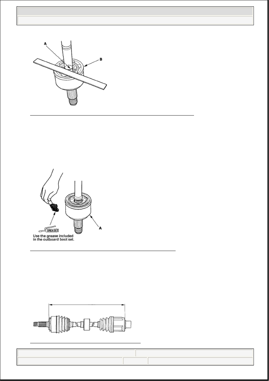
Fig. 46: Checking Alignment Of Paint Mark With Outboard Joint End 
Courtesy of AMERICAN HONDA MOTOR CO., INC. 

7. Pack the outboard joint (A) with the remaining joint grease included in the new joint boot set. 

Grease quantity (total)  

Outboard joint: 140-150 g (4.9-5.3 oz.)  

Fig. 47: Packing Outboard Joint With Remaining Joint Grease 
Courtesy of AMERICAN HONDA MOTOR CO., INC. 

8. Adjust the length of the driveshafts to these measurements, then adjust the boots to halfway between 

full compression and full extension. Make sure the ends of the boots seat in the groove of the 
driveshaft and joint. 

Right driveshaft: 532-537 mm (20.94-21.14 in.)  

Fig. 48: Identifying Right Driveshaft Dimension 
Courtesy of AMERICAN HONDA MOTOR CO., INC.


2007 Acura RL 

2005-08 DRIVELINE/AXLES Driveline/Axle - RL


me 


Friday, June 05, 2009 3:01:08 PM

Page 22 

© 2005 Mitchell Repair Information Company, LLC. 

Left driveshaft: 549-554 mm (21.61-21.81 in.)

Fig. 49: Identifying Left Driveshaft Dimension 
Courtesy of AMERICAN HONDA MOTOR CO., INC. 

9. Fit the boot (A) ends onto the driveshaft (B) and outboard joint (C). 

Fig. 50: Identifying Boot Ends, Driveshaft And Outboard Joint 
Courtesy of AMERICAN HONDA MOTOR CO., INC. 

10. Close the ear portion (A) of the band with commercially available boot band pincers Kent-Moore J-

35910 or equivalent (B). 

Fig. 51: Identifying Ear Portion Of Band 
Courtesy of AMERICAN HONDA MOTOR CO., INC. 

11. Check the clearance between the closed ear portion of the band. If the clearance is not within the 

standard, close the ear portion of the band tighter. 


2007 Acura RL 

2005-08 DRIVELINE/AXLES Driveline/Axle - RL


me 


Friday, June 05, 2009 3:01:08 PM

Page 23 

© 2005 Mitchell Repair Information Company, LLC. 

Fig. 52: Checking Clearance Between Closed Ear Portion Of Band 
Courtesy of AMERICAN HONDA MOTOR CO., INC. 

12. Repeat steps 10 and 11 for the band on the other end of the boot.  

FRONT DRIVESHAFT INSTALLATION 

1. Apply grease to the contact area (A) of the outboard joint and front wheel bearing. 

Fig. 53: Identifying Front Driveshaft Contact Area 
Courtesy of AMERICAN HONDA MOTOR CO., INC. 

2. Install a new set ring in the set ring groove of the driveshaft (left driveshaft). 

NOTE:

The grease helps prevent excessive noise or vibration.


2007 Acura RL 

2005-08 DRIVELINE/AXLES Driveline/Axle - RL


me 


Friday, June 05, 2009 3:01:08 PM

Page 24 

© 2005 Mitchell Repair Information Company, LLC. 

Fig. 54: Identifying Set Ring Groove Of Driveshaft (Left Driveshaft) 
Courtesy of AMERICAN HONDA MOTOR CO., INC. 

3. Apply 0.5-1.0 g (0.02-0.04 oz.) of grease to the whole splined surface (A) of the right driveshaft. 

After applying grease, remove the grease from the splined grooves at intervals of 2-3 splines and from 
the set ring groove (B) so that air can bleed from the intermediate shaft. 

Fig. 55: Identifying Whole Splined Surface And Ring Groove 
Courtesy of AMERICAN HONDA MOTOR CO., INC. 

4. Clean the areas where the driveshaft contacts the differential thoroughly with brake cleaner, and dry 

with compressed air. Do not wash the rubber parts with solvent. Insert the inboard end (A) of the 
driveshaft into the differential (B) or intermediate shaft (C) until the set ring (D) locks in the groove 
(E). 


2007 Acura RL 

2005-08 DRIVELINE/AXLES Driveline/Axle - RL


me 


Friday, June 05, 2009 3:01:08 PM

Page 25 

© 2005 Mitchell Repair Information Company, LLC. 


Content   ..  432  433  434  435   ..