Volvo XC40 Twin Engine (2020 year). Manual in english - page 32
 

  Index      Manuals     Volvo XC40 Twin Engine (2020 year). Manual in english


Search            copyright infringement  


Content      ..     30      31      32      33     ..


Volvo XC40 Twin Engine (2020 year). Manual in english - page 32


||

WHEELS AND TYRES

* Option/accessory.

548

IMPORTANT

When the jack

*

 is not in use it must be

stored in its storage space under the
cargo area floor.

The jack included with the car is only
designed for occasional, short-term
use, such as when changing a wheel
after a puncture. Only the jack belong-
ing to the specific model is to be used
to jack up the car. If the car is to be
jacked up more often, or for a longer
time than is required just to change a
wheel, use of a garage jack is recom-
mended. In this instance, follow the
instructions for use that come with the
equipment.

Removing a wheel

Read through all instructions before begin-
ning. Take out the tools needed before jacking
up the car.

1. Set up the warning triangle and activate

the hazard warning lights if a tyre is being
changed in a trafficked location.

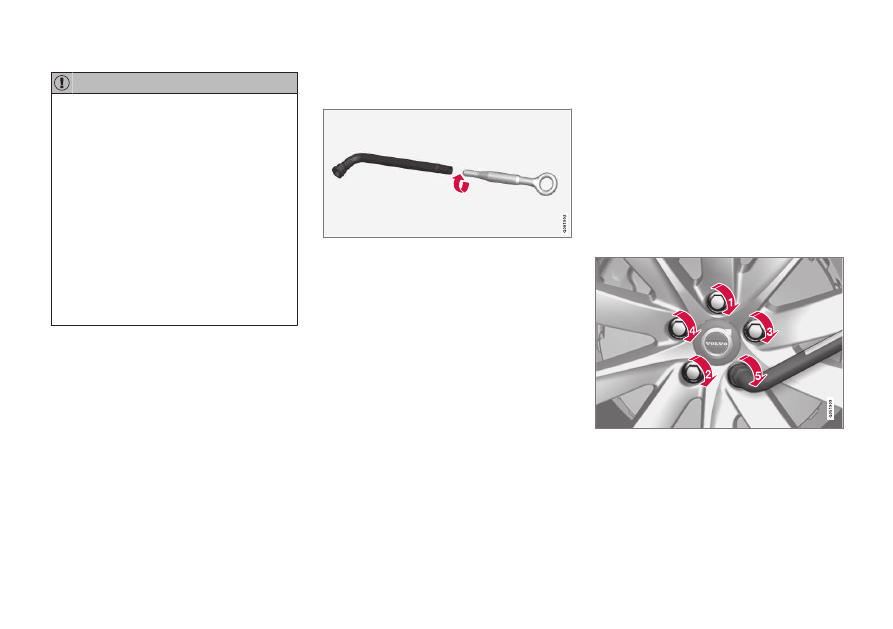
2. Screw together the towing eye with the

wheel wrench to the stop position.

3. Remove the plastic caps from the wheel

bolts with the intended tool.

4. With the car still on the ground, use the

wheel bolt wrench/towing eye to undo the
wheel bolts ½-1 turn by pressing down-
wards (anticlockwise). Always start with
the lockable wheel bolts

*

.

5. Follow the instructions for how to safely

raise the car with the jack.

6. Raise the car high enough to allow the

wheel to be removed to move freely.
Remove the wheel bolts and lift off the
wheel.

Mounting a wheel

1. Clean the surfaces between wheel and

hub.

2. Put on the wheel. Tighten the wheel bolts

thoroughly.

Do 

not

 use lubricant on the threads of the

wheel bolts.

3. Lower the car so that the wheels cannot

rotate.

4. Tighten the wheel bolts crosswise. It is

important that the wheel bolts are tight-
ened properly. Tighten to 140 Nm
(103 foot-pound). Check the tightening
torque with a torque wrench.

5. Refit the plastic caps on the wheel bolts.

6. Check the tyre pressure and save the new

tyre pressure in the system for tyre pres-
sure monitoring

*

.

-------------------------------------------------------------------------------------------------------------------------------------------------------------

WHEELS AND TYRES

* Option/accessory.

549

WARNING

The wheel bolts may need to be re-tight-

ened several days after the wheel change.

Temperature differences and vibration may

mean that they are not attached equally as

tightly.

NOTE

After a tyre has been inflated, always
refit the dust cap in order to avoid
damage to the valve from gravel, dirt,
etc.

Only use plastic dust caps. Metal dust
caps can rust and become difficult to
unscrew.

Related information

Warning triangle (p. 574)

Raise the car (p. 581)

Tool kit (p. 549)

Saving a new tyre pressure in the monitor-
ing system

*

 (p. 544)

Tool kit

Tools that can be useful during towing, wheel
changes or similar are found in the car's
cargo area.

All tools are located in the foam block under the

cargo area floor.

Jack

*

Tool for removing the plastic caps from
the wheel bolts
Funnel for filling fluids

Wheel wrench

*

 and towing eye

If the car is fitted with a spare wheel

*

, there is

a jack and a wheel bolt wrench.

Related information

Folding up the cargo area floor (p. 571)

Changing wheel (p. 547)

Jack

*

 (p. 550)

Emergency puncture repair kit (p. 554)

Fitting and removing the towing eye
(p. 469)

-------------------------------------------------------------------------------------------------------------------------------------------------------------

WHEELS AND TYRES

* Option/accessory.

550

Jack

*

The jack can be used to raise the car, for
example, to change to a wheel.

IMPORTANT

When the jack

*

 is not in use it must be

stored in its storage space under the
cargo area floor.

The jack included with the car is only
designed for occasional, short-term
use, such as when changing a wheel
after a puncture. Only the jack belong-
ing to the specific model is to be used
to jack up the car. If the car is to be
jacked up more often, or for a longer
time than is required just to change a
wheel, use of a garage jack is recom-
mended. In this instance, follow the
instructions for use that come with the
equipment.

The jack needs to be cranked together to the
correct position in order to have space.

Related information

Folding up the cargo area floor (p. 571)

Tool kit (p. 549)

Raise the car (p. 581)

Wheel bolts

Wheel bolts are used to attach the wheels to
the hubs.

Only use rims that are tested and approved by
Volvo and which are Volvo genuine accesso-
ries.

Check the tightening torque of the wheel bolts
with a torque wrench.

Do 

not

 use lubricant on the threads of the

wheel bolts.

WARNING

The wheel bolts may need to be re-tight-

ened several days after the wheel change.

Temperature differences and vibration may

mean that they are not attached equally as

tightly.

IMPORTANT

The wheel bolts must be tightened to
140 Nm. (103 foot-pound). Overtightening
or loose tightening may damage the nuts
and the bolts.

Lockable wheel bolt kit

*

To loosen or tighten the lockable wheel bolts
– turn the wrench in the lock bolt until it fully
engages in the code grooves. Always start
with the lockable wheel bolts if the wheel shall

-------------------------------------------------------------------------------------------------------------------------------------------------------------

WHEELS AND TYRES

}}

* Option/accessory.

551

be removed. When fitting the wheel, finish
with the lock screw.

IMPORTANT

Remember not to use bending force when
you loosen/tighten the wheel bolts. This
could damage the code groove in the lock
bolt and the wheel wrench and so make it
impossible to fit/remove the wheel.

When the wheel wrench is not in use it must
be stored in its place in the foam block under
the cargo area floor. It is important to remem-
ber this if the car is due to visit a workshop in
order to have the tool available. If you lose the
wrench, contact your Volvo dealer.

Related information

Changing wheel (p. 547)

Tool kit (p. 549)

Spare wheel

*

The spare wheel, the Temporary Spare type,
can be used to temporarily replace a punc-
tured normal wheel.

The spare wheel is only designed for tempo-
rary use. Replace it with a normal wheel as
soon as possible.

The car's driving characteristics can be
changed when the spare wheel is used and
the ground clearance is reduced. Do not wash
the car in an automatic car wash if the
Temporary Spare is being used.

Recommended tyre pressure must be main-
tained regardless of the position of the tempo-
rary spare wheel on the car.

If the spare wheel is damaged, a new one can
be purchased from a Volvo dealer.

WARNING

Never drive faster than 80 km/h
(50 mph) with a spare wheel fitted on
the car.

The car must never be driven fitted
with more than one "Temporary Spare"
wheel.

The car may have different driving cha-
racteristics while driving with the spare
wheel. The spare wheel must be
replaced with a normal wheel as soon
as possible.

The spare wheel is smaller than the
normal wheel, which affects the car's
ground clearance. Look out for high
kerbs and do not machine-wash the
car.

Follow the manufacturer's recom-
mended tyre pressure for the spare
wheel.

On all-wheel drive cars, the drive on
the rear axle can be disengaged.

If the spare wheel is fitted to the front
axle then it is not possible to use snow
chains at the same time.

The spare wheel must not be repaired.

-------------------------------------------------------------------------------------------------------------------------------------------------------------

||

WHEELS AND TYRES

* Option/accessory.

552

IMPORTANT

The car must not be driven with tyres of
different sizes or with a spare wheel other
than the one supplied with the car. Using
different-sized wheels can cause serious
damage to the car's transmission.

Related information

Changing wheel (p. 547)

Recommended tyre pressure (p. 542)

Handling the spare wheel

*

Follow these instructions for handling the
spare wheel.

The illustration is generic and appearance may differ.

The spare wheel is stored in a bag and must
be secured with two straps on the floor of the
cargo area while driving. The straps must be
tensioned crosswise over the wheel and
attached in the car's four load retaining eye-
lets.

Tools for changing wheels are located under
the cargo area floor.

Related information

Spare wheel

*

 (p. 551)

Folding up the cargo area floor (p. 571)

Tool kit (p. 549)

Changing wheel (p. 547)

Winter tyres

Winter tyres are adapted for winter road con-
ditions.

Volvo recommends winter tyres with particu-
lar dimensions. Tyre dimensions are depend-
ent on engine variant. When driving on winter
tyres, the correct type of tyres must be fitted
to all four wheels.

Tips for changing to winter tyres

When summer and winter wheels are
changed, mark which side of the car they were
mounted on, for example 

L

 for left and 

R

 for

right.

Contact a Volvo dealer for advice about which
wheel rim and tyre types are most suitable.

Studded tyres

Studded winter tyres should be run in gently
for 500-1000 km (300-600 miles), so the
studs settle properly into the tyres. This gives
the tyre, and especially the studs, a longer
service life.

NOTE

Laws regarding the use of studded tyres
may vary. Always follow local laws and
regulations.

Tread depth

Road conditions with ice, slush and low tem-
peratures place considerably higher demands

-------------------------------------------------------------------------------------------------------------------------------------------------------------

WHEELS AND TYRES

}}

}}

553

on tyres than summer conditions. Volvo there-
fore recommends not to drive on winter tyres
that have a tread depth of less than 4 mm
(0.15 inches).

Related information

Changing wheel (p. 547)

Winter driving (p. 450)

Tread wear indicators on the tyres
(p. 540)

Approved wheel and tyre sizes (p. 649)

Volvo Cars support site (p. 21)

Snow chains

Use of snow chains and/or winter tyres can
help to improve the traction in winter condi-
tions.

Volvo recommends that snow chains are not
used on wheel dimensions greater than
18 inches.

WARNING

Use Volvo genuine snow chains or equiva-

lent chains designed for the car model, and

tyre and rim dimensions. Only 

single-sided

snow chains are permitted.
In the event of uncertainty about the show

chain, Volvo recommends that an author-

ised Volvo workshop should be contacted.

The wrong snow chains may cause serious

damage to the car and lead to an accident.

IMPORTANT

Snow chains can be used on the car with
the following restrictions:

Always follow the mounting instruc-
tions from the manufacturer carefully.
Fit the chains as tensioned as possible
and tension them at regular intervals.

Snow chains must only be used on the
front wheels (also applies to all-wheel
drive cars).

In some cases, snow chains must NOT
be used, such as if accessory, after-
market or "special" tyres and wheels
are fitted that have a different size to
the original tyres and wheels. Suffi-
cient distance must be maintained
between the chains and brakes, sus-
pension and body components.

Check local regulations with regard to
using snow chains before fitting them.

Never exceed the chain manufacturer's
specified maximum speed. You must
never exceed 50 km/h (30 mph) under
any circumstances.

Avoid bumps, holes or sharp turns
when driving with snow chains.

Avoid driving on bare ground as this
wears out both the snow chains and
tyres.

-------------------------------------------------------------------------------------------------------------------------------------------------------------

||

WHEELS AND TYRES

* Option/accessory.

554

Driving with snow chains may have a
negative effect on the car's driving
characteristics. Avoid fast or sharp
turns, as well as braking with locked
wheels.

Some types of chain that are firmly
tensioned affect brake components
and must therefore NOT be used.

You can obtain more information on snow
chains from a Volvo dealer.

Related information

Winter driving (p. 450)

Emergency puncture repair kit

The emergency puncture repair kit

8

, is used

to seal a puncture as well as to check and
adjust the air pressure in the tyre.

Cars equipped with spare tyre

*

 do not have

the puncture repair kit.

The puncture repair kit consists of a compres-
sor and a bottle with sealing fluid. The sealing
works as a temporary repair.

NOTE

The sealing fluid is effective at sealing tyres
with tread punctures but has limited ability
to seal tyres with sidewall punctures. Do
not use the emergency puncture repair kit
on tyres displaying larger slits, cracks or
similar damage.

NOTE

The compressor is intended for temporary
emergency puncture repair and is
approved by Volvo.

Location

The puncture repair kit is located in the foam
block under the cargo area floor.

Sealing fluid expiry date

The bottle of sealing fluid must be replaced if
the bottle's expiry date has passed (see the
decal on the bottle). Treat the old bottle as
environmentally hazardous waste.

Related information

Using a puncture repair kit (p. 555)

Inflating tyres with the compressor from
the puncture repair kit (p. 558)

Tyres (p. 536)

8

Temporary Mobility Kit (TMK)

-------------------------------------------------------------------------------------------------------------------------------------------------------------

WHEELS AND TYRES

}}

}}

555

Using a puncture repair kit

The emergency puncture repair kit (TMK

9

)

can be used to seal a puncture. Read through
all instructions before use.

Overview

Label, maximum permitted speed

Switch

Electrical cable

Bottle bracket

Pressure reducing valve

Pressure gauge

Decal, warning for wheel cover

Sealing fluid bottle

Bottle opening

Connection for bottle

Air hose

Connection valve

Connecting

WARNING

Please keep the following points in mind

when using the tyre sealing system:

The sealing fluid bottle contains 1) rub-
ber latex, natural and 2) ethanediol.
These substances are harmful if swal-
lowed.

The contents of this bottle may cause
allergic skin reactions or otherwise be
potentially harmful to the respiratory
tract, the skin, the central nervous sys-
tem, and the eyes.

Precautions:

Store out of the reach of children.

Harmful if ingested.

Avoid prolonged or repeated contact
with the skin. If sealing fluid has come
into contact with your clothes, remove
them.

Wash thoroughly after handling.

First aid:

Skin: Wash affected areas of skin with
soap and water. Get medical attention
if symptoms occur.

Eyes: Flush with plenty of water for
least 15 minutes, occasionally lifting

9

Temporary Mobility Kit

-------------------------------------------------------------------------------------------------------------------------------------------------------------

||

WHEELS AND TYRES

556

the upper and lower eyelids. Get medi-
cal attention if symptoms occur.

Inhalation: Move the exposed person
to fresh air. If irritation persists, get
medical attention.

Ingestion: Do NOT induce vomiting
unless directed to do so by medical
personnel. Get medical attention.

Disposal: Dispose of this material and
its container at a hazardous or special
waste collection point.

WARNING

Do not remove the bottle or air hose when

the puncture repair kit is being used.

1.

Preparations

Set up the warning triangle and activate
the hazard warning lights if a tyre is being
sealed in a trafficked location.

If the puncture was caused by a nail or
similar, allow this to remain in the tyre. It
helps to seal the hole.

2. Detach the decal for maximum permitted

speed that is affixed on one side of the
compressor. Affix it visibly on the wind-
screen as a reminder to observe the speed
limit. You should not drive faster than
80 km/h (50 mph) after the emergency
tyre repair kit has been used.

In addition, remove the warning decal and
attach it firmly to the side of the wheel so
that it doesn't fall off.

3. Check that the switch is in position 

0

(Off), and locate the electrical cable and
the air hose.

4. Fit the sealing fluid bottle in the compres-

sor so that the red arrows on the com-
pressor and bottle meet, and then turn
clockwise until it clicks.

The bottle is equipped with a non-return
valve which means that the fluid does not
come out unless it is fitted in the com-
pressor.

5. Attach the air hose to the bottle's opening

and turn clockwise until it clicks.

6. Unscrew the tyre's dust cap and screw in

the air hose's valve connection to the bot-
tom of the thread on the tyre's air valve.

7.

Begin puncture repair

Connect the electrical cable to the closest
12 V socket and start the car.

NOTE

Make sure that none of the other 12 V
sockets is in use when the compressor is
operating.

WARNING

Do not leave children in the car without

supervision when the engine is running.

WARNING

Inhaling car exhaust fumes could result in

danger to life. Never leave the engine run-

ning in sealed areas or areas that lack suffi-

cient ventilation.

-------------------------------------------------------------------------------------------------------------------------------------------------------------

WHEELS AND TYRES

}}

557

8. Start the compressor by flicking the

switch to position 

I

 (On).

When the compressor starts, the pressure
can increase up to 6 bar (88 psi), but the
pressure drops after about 30 seconds.

WARNING

Never stand next to the tyre when the

compressor is running. If cracks or uneven-

ness arise then the compressor must be

switched off immediately. The journey

should not be continued. Call roadside

assistance for recovery to a tyre centre.

Volvo recommends an authorised tyre cen-

tre.

9. Inflate the tyre for 7 minutes.

IMPORTANT

The compressor must not be operated for
longer than 10 minutes - risk of overheat-
ing.

10. Switch off the compressor to check the

pressure on the pressure gauge. Minimum
pressure is 1.8 bar (22 psi) and maximum
is 2.5 bar (36 psi). Release air using the
pressure reducing valve if the tyre pres-
sure is too high.

To access the pressure reducing valve, the
sealing fluid bottle must first be removed.
Remove the bottle in the following order:

1. Remove the air hose from the tyre

valve.

2. Remove the air hose from the bottle.
3. Remove the bottle from the compres-

sor.

4. Refit the air hose directly in the com-

pressor.

5. Refit the air hose to the tyre valve.
6. Release air using the pressure reducing

valve.

WARNING

If the pressure is below 1.8 bar (22 psi)

then the hole in the tyre is too big. The jour-

ney should not be continued. Call roadside

assistance for recovery to a tyre centre.

Volvo recommends an authorised tyre cen-

tre.

11. Switch off the compressor and detach the

electrical cable.

12. Unscrew the air hose from the tyre valve

and refit the dust cap on the tyre.

NOTE

After a tyre has been inflated, always
refit the dust cap in order to avoid dam-
age to the valve from gravel, dirt, etc.

Only use plastic dust caps. Metal dust
caps can rust and become difficult to
unscrew.

13. Clean the air hose before putting it away

and be careful that there is no leakage of
sealing fluid.

14. As soon as possible, drive at least 3 km

(2 miles) at a maximum speed of 80 km/h
(50 mph) so that the sealing fluid can seal
the tyre, and then perform a follow-up
check.

WARNING

Sealant will spurt out of the puncture dur-

ing the first few rotations of the tyre. Make

sure that nobody is standing near the car

and gets the sealing fluid splashed onto

them when the car is driven away. The dis-

tance should be at least 2 metres (7 feet).

-------------------------------------------------------------------------------------------------------------------------------------------------------------

||

WHEELS AND TYRES

558

15.

Follow-up inspection

Connect the air hose on the tyre valve and
screw in the valve connection to the bot-
tom of the tyre valve's thread. The com-
pressor must be switched off.

16. Read the tyre pressure on the pressure

gauge.

If it is below 1.3 bar (19 psi) then the
tyre is insufficiently sealed. The journey
should not be continued. Call roadside
assistance for recovery.

If the tyre pressure is higher than
1.3 bar (19 psi), the tyre must be infla-
ted to the pressure specified in accord-
ance with the tyre pressure label on the
driver's side door pillar (1 bar = 100 kPa
= 14.5 psi). Release air using the pres-
sure reducing valve if the tyre pressure
is too high.

WARNING

Check the tyre pressure regularly.

Volvo recommends that the car is driven to the
nearest authorised Volvo workshop for the
replacement/repair of the damaged tyre.
Advise the workshop that the tyre contains
sealing fluid.

The sealing fluid bottle and hose must be
replaced after use. Volvo recommends that
these replacements be performed by an
authorised Volvo workshop.

WARNING

Maximum mileage with tyres containing

sealing fluid is 200 km (120 miles).

NOTE

The compressor is an electrical device. Fol-
low local regulations related to waste man-
agement.

Related information

Recommended tyre pressure (p. 542)

Emergency puncture repair kit (p. 554)

Inflating tyres with the compressor from
the puncture repair kit (p. 558)

Inflating tyres with the compressor

from the puncture repair kit

The car's original tyres can be inflated using
the compressor in the emergency puncture
repair kit.

1. The compressor must be switched off.

Make sure that the switch is in position 

0

(Off), and take out the electrical cable and
the air hose.

2. Attach the air hose directly into the com-

pressor's bottle bracket and turn clock-
wise until it clicks.

Move the warning decal to the side of the
compressor. It does not need to be
attached to the wheel cover unless the
sealing fluid is used.

3. Unscrew the tyre's dust cap and screw in

the air hose's valve connection to the bot-
tom of the thread on the tyre's air valve.

-------------------------------------------------------------------------------------------------------------------------------------------------------------

WHEELS AND TYRES

559

4. Connect the electrical cable to the closest

12 V socket and start the car.

WARNING

Inhaling car exhaust fumes could result in

danger to life. Never leave the engine run-

ning in sealed areas or areas that lack suffi-

cient ventilation.

WARNING

Do not leave children in the car without

supervision when the engine is running.

5. Start the compressor by flicking the

switch to position 

I

 (On).

IMPORTANT

Risk of overheating. The compressor must
not run for more than 10 minutes.

6. Inflate the tyre to the pressure specified

on the tyre pressure label on the driver
side door pillar. Release air using the pres-
sure reducing valve if the tyre pressure is
too high.

7. Switch off the compressor. Detach the air

hose and the electrical cable.

8. Refit the dust cap on the tyre.

NOTE

After a tyre has been inflated, always
refit the dust cap in order to avoid dam-
age to the valve from gravel, dirt, etc.

Only use plastic dust caps. Metal dust
caps can rust and become difficult to
unscrew.

NOTE

The compressor is an electrical device. Fol-
low local regulations related to waste man-
agement.

Related information

Recommended tyre pressure (p. 542)

Using a puncture repair kit (p. 555)

Emergency puncture repair kit (p. 554)

-------------------------------------------------------------------------------------------------------------------------------------------------------------

LOADING, STORAGE AND PASSENGER COMPARTMENT

* Option/accessory.

562

Passenger compartment interior

Overview of the passenger compartment's
interior and storage locations.

Front seat

Storage compartment in door panel, card holder on
left of steering wheel, storage under driver's seat

1

,

sun visor and glovebox with extensible hook.

Storage compartment for legroom, electrical socket
and USB port above the wireless phone charger

*

,

cup holder and storage under armrest in tunnel con-

sole.

Rear seat

Storage compartment in the door panel, cup holder

*

in the centre seat backrest, storage pocket

*

 on the

front seat backrest and also USB ports

*

 in the tunnel

console.

WARNING

Keep loose objects such as mobile phones,

cameras, remote controls for accessories,

etc. in the glove compartment or other

compartments. Otherwise they may injure

people in the car in the event of sudden

braking or a collision.

IMPORTANT

Keep in mind that high gloss surfaces, for
example, are easily scratched by metal
objects. Do not place keys, phones and
other items on sensitive surfaces.

Related information

Emptying the ashtray

*

 (p. 564)

Using the cigarette lighter

*

 (p. 563)

Electrical sockets (p. 564)

Using the glovebox (p. 566)

Sun visors (p. 567)

Tunnel console (p. 563)

Wireless phone charger

*

 (p. 512)

Connecting a device via USB port (p. 495)

1

A maximum of 1 kg (2.2 lbs) can be stored here.

-------------------------------------------------------------------------------------------------------------------------------------------------------------

LOADING, STORAGE AND PASSENGER COMPARTMENT

}}

* Option/accessory.

563

Tunnel console

The tunnel console is located between the
front seats.

Storage compartment with cup holder.

Storage compartment under the armrest.

Climate controls for the rear seat climate
functions

*

 or storage compartment. There

is also a USB port underneath

*

.

WARNING

Keep loose objects such as mobile phones,

cameras, remote controls for accessories,

etc. in the glove compartment or other

compartments. Otherwise they may injure

people in the car in the event of sudden

braking or a collision.

IMPORTANT

Keep in mind that high gloss surfaces, for
example, are easily scratched by metal
objects. Do not place keys, phones and
other items on sensitive surfaces.

NOTE

One of the detectors for the alarm

*

 is

located under the tunnel console's cup
holder. Avoid leaving coins, keys and other
metal objects in the cup holder, since this
may trigger the alarm.

NOTE

The USB sockets can be used for charging
a mobile phone or tablet, for example. Only
the front USB input can be used to play
media in the car's audio system.

Related information

Emptying the ashtray

*

 (p. 564)

Using the cigarette lighter

*

 (p. 563)

Passenger compartment interior (p. 562)

Electrical sockets (p. 564)

Climate controls (p. 193)

Using the cigarette lighter

*

The cigarette lighter can be a complement to
the 12 V socket in the front section of the tun-
nel console.

Cigarette lighter in tunnel console, front seat.

1. Press the button on the lighter.

> The button jumps up when the lighter

starts to glow.

2. Pull the lighter out from the socket and

use the glow to give a light.

3. Refit the lighter in the socket.

WARNING

Take care when the lighter is activated so

that the glowing part does not, for exam-

ple, damage the interior or injure passen-

gers.

-------------------------------------------------------------------------------------------------------------------------------------------------------------

||

LOADING, STORAGE AND PASSENGER COMPARTMENT

* Option/accessory.

564

Related information

Passenger compartment interior (p. 562)

Emptying the ashtray

*

 (p. 564)

Emptying the ashtray

*

When there is a cigarette lighter fitted in the
car there is a detachable ashtray in the tunnel
console.

1. Detach the ashtray by pulling it straight up

and empty the contents.

2. Refit the ashtray in the tunnel console.

WARNING

Exercise caution with smouldering glow

and ash so that they do not damage the

interior or injure passengers, for example.

Only extinguish cigarettes on the intended

surface.

Related information

Passenger compartment interior (p. 562)

Using the cigarette lighter

*

 (p. 563)

Electrical sockets

There is one 12 V electrical socket in the tun-
nel console and one 12 V electrical socket

*

 in

the cargo area.

If a problem occurs with an electrical socket,
contact a workshop - an authorised Volvo
workshop is recommended.

12 V electrical socket

12 V electrical socket in tunnel console, front seat.

The 12 V sockets can be used for various
accessories designed for this, such as music
players, cooler boxes and mobile phones.

-------------------------------------------------------------------------------------------------------------------------------------------------------------

LOADING, STORAGE AND PASSENGER COMPARTMENT

}}

* Option/accessory.

565

12 V electrical socket in cargo area

*

.

Related information

Passenger compartment interior (p. 562)

Using electrical sockets (p. 565)

Using electrical sockets

12 V sockets can be used for various acces-
sories designed for this, such as music play-
ers, cooler boxes and mobile phones.

For the sockets to supply current, the car's
electrical system must be set in the lowest
ignition position 

I

. The sockets are then active

as long as the starter battery level does not
become too low.

If the engine is switched off and the car is
locked, the sockets are deactivated. If the
engine is switched off and the car is not
locked, or is locked with double lock tempo-
rarily deactivated, then the sockets continue to
be active for a further seven minutes.

NOTE

Remember that use of the electrical socket
with the engine switched off entails a risk
of discharging the starter battery, which
can limit functionality.

Accessories that are connected to the elec-
trical sockets may be activated even when
the car's electrical system is disconnected
or if preconditioning is used. For this rea-
son, disconnect the connectors when they
are not in use in order to avoid the starter
battery being discharged.

WARNING

Do not use accessories with large or
heavy connectors - they can damage
the socket or come loose when driving.

Do not use accessories that can cause
interference to the car's radio receiver
or electrical system for example.

Position the accessory so that it is not
at risk of injuring the driver or passen-
gers in the event of heavy braking or
collision.

Keep an eye on connected accessories
as they can generate heat that can
burn passengers or the interior.

Using 12 V sockets

1. Remove the blanking plug (tunnel con-

sole) or fold down the cover (cargo area)
in front of the socket and plug in the
accessory's connector.

2. Unplug the accessory's connector and

refit the blanking plug (tunnel console) or
fold up the cover (cargo area) when the
socket is not in use or if the socket is left
unattended.

IMPORTANT

Maximum socket output is 120 W (10 A)
per socket.

-------------------------------------------------------------------------------------------------------------------------------------------------------------


Content      ..     30      31      32      33     ..