Volvo 850. Manual - part 62


  Index      Volvo     Volvo 850 - service repair manual 1995-1996 year


Search            


Content   ..  60  61  62  63   ..


Volvo 850. Manual - part 62


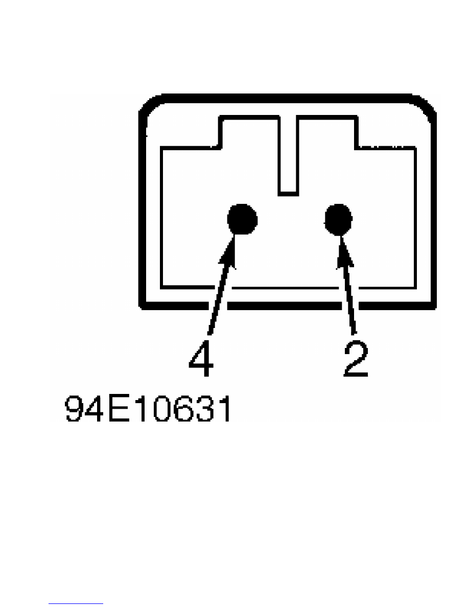
Fig. 9:  Identifying Duct Temperature Sensor Terminals

Courtesy of Volvo Cars of North America.

         DTC 1-3-2 & 1-3-4 DRIVER’S OR PASSENGER’S SIDE DUCT

         TEMP. SENSOR CIRCUIT OPEN OR SHORTED TO POWER

         1) If DTC 1-3-2 and 1-3-4 are both present, check for open

circuit in duct temperature sensor common ground (Brown wire). If DTC

1-3-2 and 1-3-4 are not both present, there is an open or short

circuit in wiring between ECC control module and duct temperature

sensor. Go to next step.

         2) Ensure ignition is off. Connect test unit between ECC

control module and A/C system connector. Check ground circuit and

repair as necessary. See DTC 1-2-1, OUTSIDE TEMP. SENSOR CIRCUIT

SHORTED TO GROUND. If ground circuits are okay, go to next step.

         3) Turn ignition on. Check driver’s side duct temperature

sensor wiring by checking voltage between test unit pins No. 56 and

47. Check passenger’s side duct temperature sensor wiring by checking

voltage between test unit pins No. 56 and 48. Voltage will vary with

duct temperature, but generally should be in 0-3 volt range.

         4) If voltmeter indicates 5 volts, check duct temperature

sensor wiring for an open circuit. Go to next step. If voltmeter

indicates 12 volts, check wiring for short to voltage between

connector terminal No. 2 (Green or Yellow wire) and ECC control module

terminal C1 (driver’s side) or C2 (passenger’s side). See  Figs. 8 and

10.

         5) Ensure ignition is off. Disconnect ECC control module, but

leave test unit connected to control module connector. Disconnect

connector from each duct temperature sensor. Connect jumper wire

between duct temperature sensor connector terminals.

         6) Check driver’s side duct temperature sensor wiring by

measuring resistance between test unit pins No. 56 and 47. Check

passenger’s side duct temperature sensor wiring by measuring

resistance between test unit pins No. 56 and 48.

         7) If continuity is present, wiring is okay but duct

temperature sensor has an open circuit. Replace duct temperature

sensor. If continuity is not present, duct temperature sensor is okay

but an open circuit is present in wiring. Repair wiring for an open

circuit.

Fig. 10:  Identifying ECC Control Module Terminals

Courtesy of Volvo Cars of North America.

         DTC 1-3-5 NO ENGINE TEMPERATURE FREQUENCY SIGNAL

         1) Run engine and check whether temperature gauge in

instrument cluster works. If temperature gauge works, engine

temperature signal is reaching instrument panel, but Green/Gray wire

between ECC control module terminal A23 and instrument cluster has an

open circuit. See Fig. 10.

         2) If temperature gauge does not work, temperature sensor

wiring may be shorted or engine temperature signal may be absent from

engine management system.

         3) To check wiring, turn ignition off. Check Green/Gray wire

between ECC control module terminal A23 and instrument cluster for a

short to ground or voltage. If no fault is found, problem may be in

engine management system. See the G - TESTS W/CODES article in the

ENGINE PERFORMANCE section.

         DTC 1-4-1 & 1-4-3 DRIVER’S OR PASSENGER’S SIDE TEMP.

         SWITCH FAULTY CONTROL SIGNAL

         These codes may be caused by an internal fault in ECC control

module, temperature switch, or internal wiring. Erase DTCs. Turn

ignition off, then on. Test ECC system. See  TEST MODE 1 through 4

under TROUBLE SHOOTING. Check if DTCs return. If DTCs return, replace

ECC control module. Perform self-adjustment of damper motor limit

positions under TEST MODE 4.

         DTC 1-4-5 AIR DISTRIBUTION SWITCH FAULTY CONTROL SIGNAL

         Code may be caused by an internal fault in ECC control

module, air distribution switch, or internal wiring. Erase DTCs. Turn

ignition off, then on. Test ECC system. See  TEST MODE 1 through 4

under TROUBLE SHOOTING. Check if DTCs return. If DTCs return, replace

ECC control module. Perform self-adjustment of damper motor limit

positions under TEST MODE 4.

         DTC 1-5-1 & 1-5-2 FAN SPEED SENSOR CONTROL SIGNAL MISSING,

         SIGNAL TOO HIGH OR SIGNAL SHORTED TO GROUND

         Codes may be caused by an internal fault in ECC control

module, fan speed switch, or internal wiring. Erase DTCs. Turn

ignition off, then on. Test ECC system. See  TEST MODE 1 through 4

under TROUBLE SHOOTING. Check if DTCs return. If DTCs return, replace

ECC control module. Perform self-adjustment of damper motor limit

positions under TEST MODE 4.

         DTC 2-1-1, 2-2-1, 2-3-1, 2-3-3 & 2-3-5 DRIVER’S OR

         PASSENGER’S SIDE DAMPER MOTOR POSITION SENSOR CIRCUIT

         OPEN OR SHORTED TO POWER

         1) Check if DTCs 1-2-2, 1-2-4, 1-2-6, 2-1-1, 2-2-1, 2-3-1, 2-

3-3 and2-3-5 are present. If all DTCs are not present, there is an

open or short circuit in a wire between ECC control unit and damper

motor which applies to DTC. See AUTOMATIC A/C-HEATER SYSTEM DIAGNOSTIC

TROUBLE CODES table, then go to next step. If all DTCs are present, an

open circuit is present in common ground at ECC terminals A9 and A10.

See Fig. 10.

         2) Ensure ignition is off. Connect test unit between ECC

control unit and control unit connector. Check ECC grounds. See DTC 1-

2-1, OUTSIDE TEMP. SENSOR CIRCUIT SHORTED TO GROUND. Also check power

supply to damper motor position sensor. See  TEST MODE 2 under TROUBLE

SHOOTING. If ECC grounds and power supply to damper motor position

sensor are okay, go to next step.

         3) Turn ignition on. Connect voltmeter between test unit pins

No. 10 and No. 17 (driver’s side damper motor), No. 18 (passenger’s

side damper motor), No. 20 (ventilation damper motor), No. 19

(floor/defrost damper motor), or No. 21 (recirculation damper motor).

         4) If voltmeter indicates 12 volts, check wiring and ECC

control unit terminals for a short to voltage. See  PIN VOLTAGE TESTS

under TESTING. If voltmeter indicates 5 volts, an open circuit is

present in wire. Go to next step.

         5) Ensure ignition is off. Disconnect ECC control module, but

leave test unit connected to ECC connector. Disconnect 6-pin damper

motor connector and install a jumper wire between connector terminals

No. 1 and 2. See Figs. 11-13. Connect an ohmmeter between test unit

pins No. 10 and 8. If ohmmeter indicates continuity, go to next step.

If ohmmeter indicates no continuity, check for open circuit in Brown

ground wire.

         6) Connect jumper wire between damper motor connector

terminals No. 2 and 3. Connect ohmmeter between test unit pins to test

respective damper motor. See DAMPER MOTOR TEST UNIT PIN NUMBERS

(RESISTANCE CHECK) table.

DAMPER MOTOR TEST UNIT PIN NUMBERS (RESISTANCE CHECK)


Pin No.                                         Damper Motor

8 & 17  .....................................  Driver’s Side

8 & 18  ..................................  Passenger’s Side

8 & 20  .......................................  Ventilation

8 & 19  .....................................  Floor/Defrost

8 & 21  .....................................  Recirculation


         7) If ohmmeter indicates continuity, wiring to damper motor

terminal No. 3 is okay, but an open circuit is present in damper motor

position sensor. Go to next step. If ohmmeter indicates no continuity,

damper motor position sensor is okay, but open circuit is present in

wire between damper motor connector terminal No. 3 and ECC control

module connector "A".

         8) Ensure ignition is off. Disconnect damper motor connector.

Connect ohmmeter between terminals No. 1 and 3. See  Fig. 11. Turn

damper motor output shaft. Ohmmeter should vary between 0-12,000 ohms.

If resistance is to specification, go to next step. If resistance is

not to specification, there is an open circuit in damper motor

position sensor.

         9) Connect ohmmeter between damper motor terminals No. 2 and

3. Turn damper motor output shaft. Ohmmeter should vary between 0-12,

000 ohms. See Fig. 11. If ohmmeter indicates no continuity, there is

an open circuit in damper motor position sensor. Replace damper motor.

Fig. 11:  Identifying Damper Motor Connector & Component Terminals

Courtesy of Volvo Cars of North America.


Content   ..  60  61  62  63   ..