Volvo 50-42LE transmission. Manual - part 26
 

  Index      Volvo     Volvo 50-42LE transmission - service repair manual 2004 year


Search            


Content   ..  24  25  26 


Volvo 50-42LE transmission. Manual - part 26


103

AUTOMATIC TRANSMISSION SERVICE GROUP

Technical Service Information

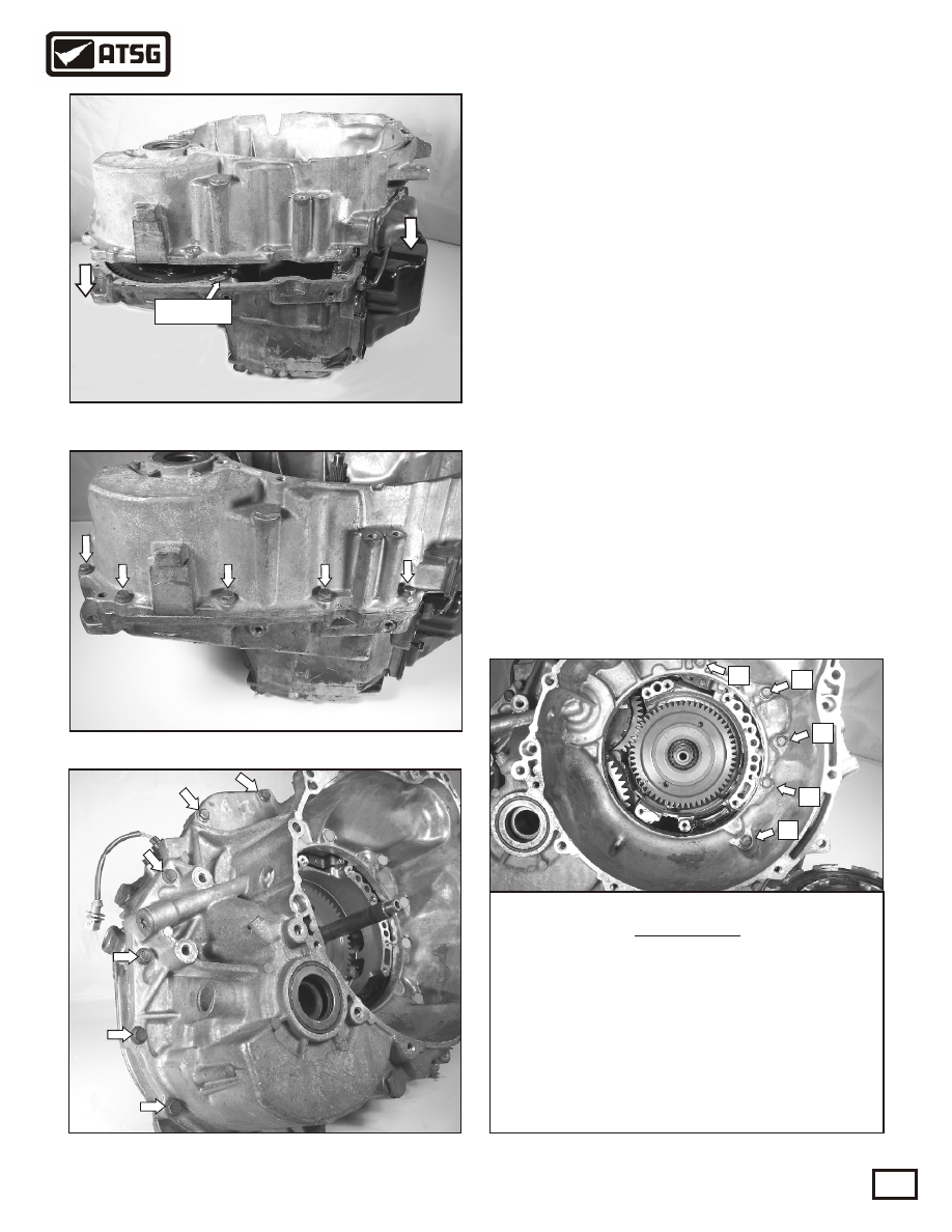
210. Apply a thin coat of sealant between the case
        half and the bell housing and assemble the bell
        housing onto the case half. See Figure 286.
211. Install the five bolts shown in Figure 287.
        Note: The bolt lengths are 30mm long.
        
Torque to 17-26 ft.lb.
212. Install the six bolts shown in Figure 288.
        Note: The bolt lengths are 30mm long.
        Torque to 17-26 ft.lb.
213. Install the five bolts as shown in Figure 289.
        Refer to the chart for the correct bolt lengths
        and torque the bolts to 17-26 ft.lb.

TRANSMISSION REASSEMBLY

CONTINUED

Continued on Page 104

Figure 286

Figure 287

Figure 288

Sealant

Figure 289

B

C

D

E

A

Bolt lengths

5 bellhousing  to case retaining bolts 

A = 30mm long

B = 35mm long

C = 35mm long
D = 30mm long

E = 45mm long

Copyright © 2004 ATSG

AUTOMATIC TRANSMISSION SERVICE GROUP

Technical Service Information

104

Copyright © 2004 ATSG

214. Stand the transmission horizontally on the
        bench as shown in Figure 290.
215. Ensure that the B2 second coast brake hub is 
        fully indexed into the clutch plates on the back
        of the pump as shown in Figure 291. Lubricate
        the pump o-ring.
216. Install the pump assembly into the case and 
        gently tap it into the case. Once the pump is 
        seated into the case, install the eight pump to
        case retaining bolts and torque to 15-22ft.lb.
        Note: The bolt lengths are 28mm long. See
        Figure 292.
217. Turn the transmission to the side and air check
        each clutch and brake to ensure proper apply.
        Install two new apply seals. See Figure 293.

TRANSMISSION REASSEMBLY

CONTINUED

Continued on Page 105

Transmission in horizontal

position on the bench

Figure 291

Figure 290

Figure 292

B4 Servo

and accumulator

B2 Brake

B3 Brake

B1 Brake

C3 Clutch

C1 Clutch

and accumulator

passage

C2 Clutch

NOTE: When air checking the C1 clutch thru

C1 port 1, you must cover C1 port 2 and vice-versa.

C1 port 1

C1 port 2

Figure 293

Case air checks

B2 second coast brake hub

Install two new

apply seals

AUTOMATIC TRANSMISSION SERVICE GROUP

Technical Service Information

105

TRANSMISSION REASSEMBLY

CONTINUED

Figure 294

Continued on Page 106

Remove the inner thrust

washer and bearing

Internal wire harness to case retainer

Figure 81

Manual shaft

218. Install a new o-ring on the plastic part of the 
        wiring harness,  install it back thru the case, 
        and place the retainer in the groove as shown
        in Figure 294.

220. Install the two connector retaining bolts and 
        torque to 14-22 ft.lb. Note: the bolt lengths
        are 20mm long.
 Install the manual lever and
        the retaining nut and torque to 7-10 ft.lb. See
        Figure 296.
221. Install the valve body on to the case and align
        the manual valve link into the manual shaft as
        shown in Figure 297.

219. Install the transmission range switch over the 
        manual shaft and align the flats on the shaft 
        with the dotted line on the transmission 
        range switch as shown in Figure 295.
        Torque bolts A and B to 14-22ft.lb.   Note: the 
        bolt lengths are as follows,  A = 21mm long 
        and B = 32mm long

Manual lever

Transmission

range switch

Figure 295

Figure 296

Flats on the

manual shaft

A

B

Figure 297

1-P

1-P

THE END OF THE MANUAL VALVE IS 

FLUSH WITH THE END OF THE VALVE 

BODY CASTING, WHEN THE SELECTOR

IS IN THE "PARK POSITION"

MANUAL VALVE

LINK

AUTOMATIC TRANSMISSION SERVICE GROUP

Technical Service Information

106

TRANSMISSION REASSEMBLY

CONTINUED

Figure 298

Copyright © 2004 ATSG

A

A

B

B

B

B

C

C

C

222. Install the 10 mm headed valve body to case
        retaining bolts as shown in Figure 298.Torque 
        to 7-11 ft.lb.  Note: bolt lengths are as follows, 
        A = 16mm long, 50mm long and C = 55mm 
        long.
223. Install the four solenoid connectors shown in
        Figure 299. Note: The internal wire colors are 
        listed below each solenoid.
224. Apply a thin coat of sealant to the case half
        and install the side pan. Install the nine pan 
        bolts and torque to 7-11ft.lb. Note: the bolt 
        lengths are 15mm long. 
Install the temperature
        sensor. See Figure 300.

S2

black

STH

tan/blue

SL

red

S1

white

Temp

sensor

Remove the 9 pan bolts

Figure 299

Figure 300


Content   ..  24  25  26