Volvo 50-42LE transmission. Manual - part 14
 

  Index      Volvo     Volvo 50-42LE transmission - service repair manual 2004 year


Search            


Content   ..  12  13  14  15   ..


Volvo 50-42LE transmission. Manual - part 14


AUTOMATIC TRANSMISSION SERVICE GROUP

Technical Service Information

55

Copyright © 2004 ATSG

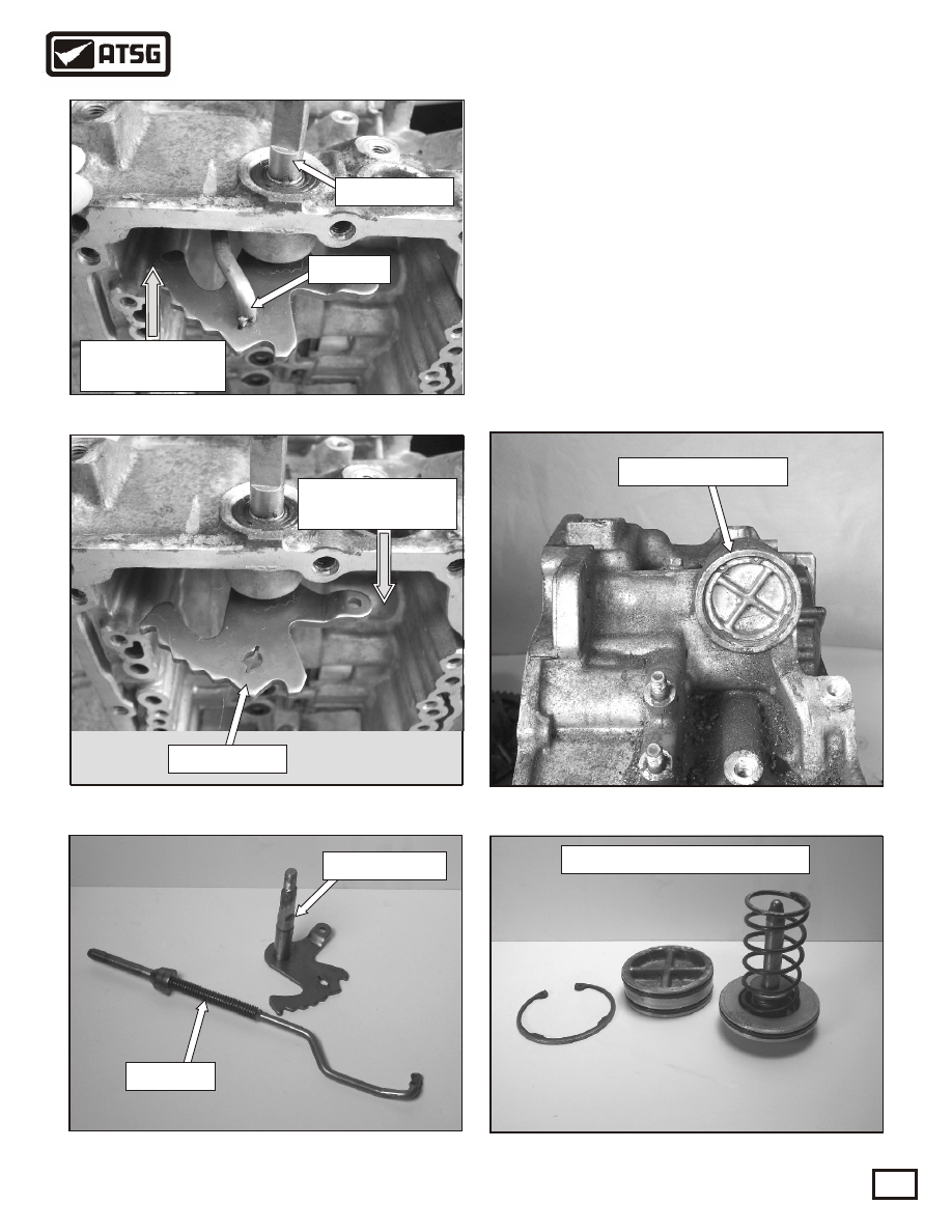
 42. Rotate the Manual shaft until the tab on the 
       park rod aligns with the slot in the in the
       manual shaft. Lift the park rod up and pull it
       forward to remove it from the case as shown in
       Figure 93.
 43. Push the manual shaft down thru the case to 
       remove it as shown in Figure 94.
 44. Refer to Figure 95 to view the manual shaft and
       the park rod removed from the case.
 45. Remove the snap ring retaining the B4 servo
       assembly into the case, as shown in Figure 96.
 46. Refer to Figure 97, to view the B4 servo and 
       it's related parts.

TRANSMISSION DISASSEMBLY

CONTINUED

B4 servo assembly

Figure 93

Figure 94

Figure 96

Figure 97

B4 servo assembly removed

Manual shaft

Park rod

Manual shaft

Push the Manual

shaft this direction

Push the park

rod this direction

Manual shaft

Park rod

Figure 95

Copyright © 2004 ATSG

AUTOMATIC TRANSMISSION SERVICE GROUP

Technical Service Information

56

 47. Remove the snap ring and B2 clutch assembly
       as shown in Figure 98.
 48. Remove the snap ring and pressure plate above
       the B1 clutch as shown in Figure 99. Caution:
       The pressure plate is spring loaded in the
       direction facing you.
 
 49. Remove the return spring assembly as shown in 
       Figure 100.
 50. Remove the remaining B1 clutch assembly as
       shown in Figure 101.
 51. Remove the pump to B2 second coast brake 
       hub thrust washer as shown in Figure 102.

SUB-ASSEMBLIES

"PUMP"

Figure 98

Figure 99

Figure 100

Figure 101

Figure 102

Thrust washer

Continued on Page 57

Copyright © 2004 ATSG

B1 upper pressure plate

Return spring assembly

Remove B1 clutch assembly

B2 clutch assembly

Caution

spring loaded

AUTOMATIC TRANSMISSION SERVICE GROUP

Technical Service Information

57

 52. Using a suitable press, remove the snap ring 
       and B1 return spring assembly, as shown in 
       Figure 103.
 53. Refer to Figure 104 for piston identification.
 54. Apply compressed air to the passage shown in 
       Figure 105 and remove the B2 piston. Caution:
       Using compressed air may cause the piston to 
       jump out of the housing
.
 55. Apply compressed air to the passage shown in 
       Figure 106 and remove the B1 piston.
 56. Using a 30 torx bit, remove the 14 bolts that
       retain the piston housing to the pump. Note: 
       The bolt length for the smaller diameter bolt
       is 16mm long. The remaining bolts are 13mm
       long. 
Inspect stator bushings and replace
       as necessary. See Figure 107.
       

Continued on Page 58

B1 return spring

Figure 103

Figure 105

Figure 104

Figure 106

B1 piston

Figure 107

Apply air
pressure

SUB-ASSEMBLIES

"PUMP" CONTINUED

B2 piston

Remove

B2 piston

Apply air
pressure

Remove

B1 piston

Piston

housing

Snap ring

Smaller

diameter bolt

16mm long

Stator

bushings

AUTOMATIC TRANSMISSION SERVICE GROUP

Technical Service Information

58

 57. Remove the pump plate as shown, in Figure
       108, and check for wear or scoring. 
 58. Using a straight edge, check the pump gear to
       pump face clearance, as shown in Figure 109.
       Clearance must be between .001"-.003." The
       maximum clearance is .004." Using a feeler 
       gage check the outer pump gear to pump body
       clearance. Clearance must be between .003"
       and .006." The maximum is .008."
 59. Inspect the outer pump gear and the torque
       converter lug area for wear, as shown in 
       Figure 110.
 60. Inspect the pump body for wear, and remove
       the pump o-ring as shown in Figure 111.
 61. Check the pump bushing for wear and replace 
       the front seal, as shown in Figure 112.

Figure 108

Figure 110

Figure 112

Continued on Page 59

Pump bushing

Figure 111

Pump body check

Figure 109

.0

03

"

Pump gear clearance check

Straight edge

Feeler gage

Pump gear check

Pump plate

.0

0

3

"

SUB-ASSEMBLIES

"PUMP" CONTINUED

Pump seal

Pump o-ring


Content   ..  12  13  14  15   ..