Volkswagen Touareg (2015 year). Instruction - part 1
 

  Index      Volkswagen     Volkswagen Touareg - instruction 2015 year in english


Search            copyright infringement  


Content   ..    1  2   ..


Volkswagen Touareg (2015 year). Instruction - part 1


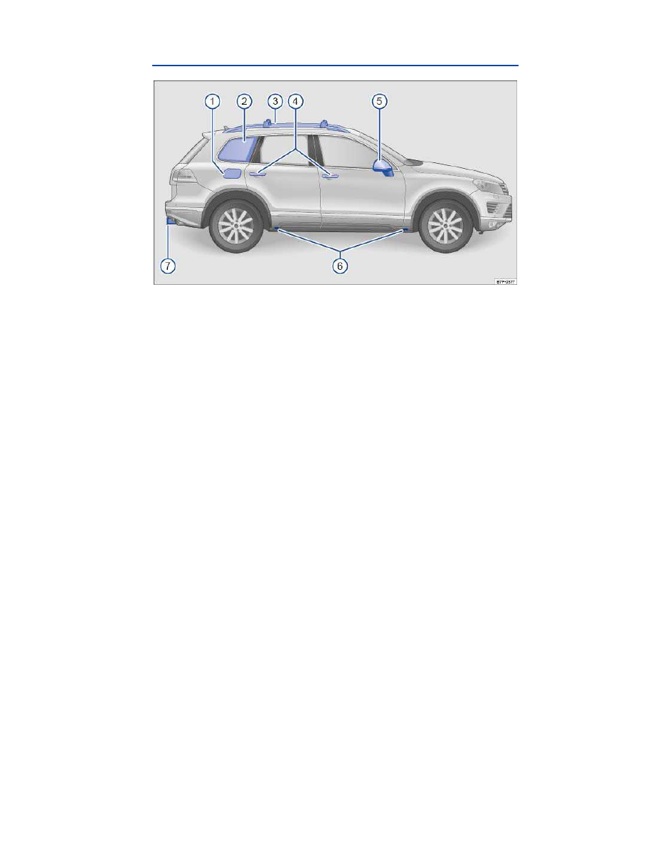
Side view 


Fig. 1 Vehicle side overview. 

Key to 

fig. 1

(1)


Fuel filler flap  

(2)


Side window with window diversity antenna for:  
–  Radio  
–  Central locking  

(3)


Roof rack  

(4)


 Outside door handles  

(5)


Outside mirror:  
–  Additional turn signal light  
–  Area view  

(6)


Lift points for the jack  

(7)


Trailer hitch/ball mount receiver  


Front view 


Fig. 2 Vehicle front overview. 

Key to 

fig. 2

(1)


Power sunroof  

(2)


Windshield area with: 
–  Rain sensor on mirror base  
–  Low-light sensor on mirror base 
–  Dynamic high beam control on mirror base  
–  Windshield wipers  

(3)


Engine hood release  

(4)


Headlights (on both left and right) ,  

(5)


Headlight washers (on left and right)  

(6)


Threaded hole for the front towing eye (on both left and right) behind covers  

(7)


Sensors for front Park Distance Control (on both left and right)  

(8)


Fog lights/static cornering lights (on both left and right)  

(9)


Radar sensors for the adaptive cruise control (ACC) (on both left and right)  

(10)

  Camera for Area View  


Rear view 


Fig. 3 Vehicle rear overview. 

Key to 

fig. 3

(1)


Roof antenna for:  
–  Mobile phone  
–  Navigation  

(2)


High-mounted brake light  

(3)


Rear window with: 
–  Rear window defroster  
–  Rear window wiper  

(4)


Taillights (on both left and right)  

(5)


Area of: 
–  Button to open the rear hatch  
–  Rear Assist camera and the Area View camera  
–  License plate lighting  

(6)


Radar sensors for Side Assist  

(7)


Sensors for rear Park Distance Control  

(8)


Threaded hole for the rear towing eye (on both left and right) behind covers  

(9)


Trailer hitch/ball mount receiver  


Driver door overview 


Fig. 4 Overview of controls in the driver door. 

Key to 

fig. 4

(1)


Door handle  

(2)


Power locking switch for locking and unlocking the vehicle        

(3)


Switch for adjusting the outside mirror:  
–  Adjusting outside mirrors           
–  Outside mirror heating   
–  Folding mirror   

(4)


Buttons for operating the power windows:  
–  Power windows 


–  Safety switch for rear power windows and electric child safety lock 


(5)


Indicator for power locking system  

(6)


Lever for releasing the engine hood  

(7)


Storage compartment  

(8)


Bottle holder  

(9)


Door light 

(10)

  Switch to unlock the rear hatch  &   

(11)

  Memory buttons for storing the driver seat and outside mirror settings   –   –   – 


Driver side overview 


Fig. 5 Driver side overview. 

Key to 

fig. 5

(1)


Instrument cluster: 
–  Instruments  
–  Display  
–  Warning and indicator lights  

(2)


Headlight switch  :  
–  Off position - - 
–  Automatic headlight activation -

–  Parking lights and low beams 


(3)


Lever for:  
–  High beams 


–  Headlight flasher 


–  Turn signals 


(4)


Lever for windshield wiper and washer:  
–  Windshield wiper 

 – 


–  Intermittent operation for windshield wipers 


–  “One-tap wiping”  x 
–  Windshield wiper 


–  Automatic wipe/wash for windshield   
–  Rear window wiper   
–  Automatic wipe/wash for rear window   
–  Lever with buttons for the Volkswagen Information System (Basic version) 

- ,  /


(5)


Multi-function steering wheel controls:  
–  Volume setting for radio, navigation system notifications, or telephone calls (if applica-

ble) 

 – 


–  Mute switching for radio or activation of voice control (if applicable) 


–  Display Phone main menu or accept telephone calls 


–  Audio, Navigation   –   
–  Control switches for the Volkswagen Information System (Premium version)  # , 

,  ∃ , 

OK , 


(6)


Ignition switch  

(7)


Dimmer control for the Instrument cluster and switch illumination    

(8)


Switch for adjusting the electric steering column  

(9)


Horn (only works when the ignition is switched on) 

(10)

  Pedals  

(11)

  Driver front airbag  

(12)

  Air vents 


(13)

  Cruise Control System (CCS) lever 

 – 

 –   – 

 – 

 – 


(14)

  Fog light button 


Upper center console 


Fig. 7 Overview of upper center console. 

Key to 

fig. 7

(1)


Air vent for indirect ventilation  

(3)


Air vents 


(2)


Storage compartment  

(4)


Radio or Radio & Navigation system (factory installed)  

(5)


Controls for: 
–  Climatronic  
–  Seat heating switch button    

(6)


Located here: 
–  Switch for emergency flashers 


–  PASSENGER AIR BAG 

   light (front airbag for front seat passenger) 

–  Park Distance Control system button 

 or  ∗   

–  Rear View camera  ∗   
–  Heated steering wheel 


Lower center console 


Fig. 8 Overview of lower center console (4MOTION). 

Key to 

fig. 8

(1)


Automatic transmission selector lever  

(2)


Button for: 
–  Electronic parking brake 


(3)


Cup holders  

(4)


Storage compartment  
–  with 12 Volt socket  

(5)


Starter button for Keyless Access locking and starting system 

 – 


(6)


Storage compartment in the center armrest  

(7)


Button for: 
–  Driving with electric motor  -


–  Anti-slip regulation (ASR)    

(8)


Rotary knob for setting drive mode (On-road / Off-road)  


Rear center console 


Fig. 10 Overview of rear center console. 

Key to 

fig. 10

(1)


Cover for: 
–  12 Volt socket  
–  115 Volt outlet  

(2)


Air vents 


(3)


Controls for: 
–  Seat heating button    

(4)


Storage compartment in the rear center console  


Front passenger side overview 


Fig. 11 Overview of the passenger side. 

Key to 

fig. 11

(1)


Passenger front airbag location in the instrument panel (approximate)  

(2)


Opening handle for the lockable glove compartment  

(3)


Air vents 


Roof console overview 


Fig. 12 Overview of the roof console. 

Key to 

fig. 12

(1)


Buttons for HomeLink

®

 Universal Transmitter  1   2   3   

(2)


3 button module  
–  Voice operation 


–  Information   
–  Assistance 


(3)


Interior and reading lights . 

(4)


Buttons for interior lights 
–  Button for Interior lights 


–  Switch for door contact 


–  Switch off interior lights    

(5)


Button for reading lights 


(6)


Switch for power sunroof  

(7)


Reading lights  

(8)


Background lighting  


Instrument Cluster 

 Introduction 

In this section you’ll find information about: 

Instrument overview


Instrument overview


Displays


Compass


Service reminder display


More information: 

  Service reminder information 

⇒ Booklet 

Warranty and Maintenance. 

  Warning and indicator lights  
  Infotainment System 
  Display of the selected gears (automatic transmission)  

  WARNING 

Driving on today's roads demands the full attention of the driver at all times. Driver distrac-
tion causes accidents, collisions and serious personal injury! 

  Never use the buttons in the instrument cluster while driving. 

Instrument overview 


Fig. 13 Instrument cluster in the instrument panel. 

 Please first read and note the introductory information and heed the WARNINGS 


Instrument explanations to 

fig. 13

(1)


Speedometer 

(2)


Tachometer (shows engine revolutions per minute in thousands, when the engine is running). 


The red zone at the end of the scale indicates maximum permissible engine rpm (revolutions 
per minute) for all gears after the break-in period. Before reaching this region, select the next 

higher selector level position  (D), or ease your foot off the accelerator 

⇒  . 

(3)


Displays  

(4)


Reset button for the trip odometer display (trip) and button to display the engine code. 

–  Push and hold the  0.0   button about 1 second in order to reset to zero. 

–  Keep the  0.0   button pushed for about 3 seconds to display the previous value. 

–  Push and hold the  0.0   button for more than 10 seconds to display the vehicle's engine 

code. You must do this when the ignition is on, but the engine is not running. 

(5)


Fuel gauge  

(6)


Engine coolant temperature display  

  NOTICE 

  To help prevent engine damage, always avoid high engine speeds, full throttle acceleration 

and heavy engine loads when the engine is cold. 

  To help prevent engine damage, the tachometer needle should only enter the red zone 

(warning zone) briefly. 

  Up-shifting early into the next higher gear saves fuel and reduces engine noise. 

Displays 


Fig. 15 In the instrument cluster display: A: Open engine hood, B: Open rear hatch, C: Open front driver side 
door, D: Open rear passenger side door. 

 Please first read and note the introductory information and heed the WARNINGS 


Depending on the vehicle model, different information may be shown in the instrument cluster display 
⇒ 

fig. 13


(4)


⇒ 

fig. 14


(4)

  Warning and information texts. 
  Odometer displays. 
  Time  
  Navigation information  
  Outside temperature. 
  Compass display  


  Open door, engine hood, or rear hatch 

⇒ 

fig. 15

  Hybrid drive information  
  AdBlue information  
  Selector lever position  
  Multi-Function Indicator (MFI) and menus for different settings  
  Service reminder display  
  Speed warning  

Warning and information texts 

The status of various vehicle functions and components is monitored when the ignition is switched on 
and while driving. Malfunctions are indicated by red and yellow warning symbols with text messages in 

the instrument cluster display (

⇒ Instrument cluster and instrument panel). In some cases, they may 

also be signaled acoustically. The display can vary depending on the instrument cluster model. 


Type of no-
tification  

Symbol 

color  

Explanation  

Priority 1 
warning 
message  

Red  

Symbol flashing or lit – sometimes with acoustic 
warnings. 

 Stop! 

⇒   

Check malfunction and take corrective action. 
Contact an authorized Volkswagen dealer or an 
authorized Volkswagen Service Facility for assis-
tance if necessary. 
Menus cannot be accessed when a priority 1 
warning message is displayed. The warning 
message will turn off automatically after a few 
seconds. You can confirm and turn off some 
warning messages using the OK button.  

Priority 2 
warning 
message  

Yellow   Symbol flashing or continuously lit – sometimes 

with acoustic warnings. 
Malfunctions or low operating fluid levels may 
cause vehicle damage and vehicle breakdown 
⇒  . 

Check malfunction as soon as possible. Contact 
an authorized Volkswagen dealer or an author-
ized Volkswagen Service Facility for assistance if 
necessary.  

Information 
text  

–  

Information about various vehicle situations.  


Odometer displays 

The odometer indicates the total distance driven by the vehicle. 

The trip odometer (trip) shows the distance driven since the last time the trip odometer was reset. 
The last digit indicates 1/10 mile (100 meters). 

Outside temperature display 

At outside temperatures below about +39 °F (+4 °C), a “snowflake symbol” (icy road warning) appears 
in the display. The symbol flashes at first, then stays on until the outside temperature rises above 

+43 °F (+6 °C) 

⇒  . 

When the vehicle is not moving or when you are driving at very low speeds, the temperature displayed 
may be slightly higher than the actual outside temperature. 

The measurement range is from -40 °F (-40 °C) to +122 °F (+50 °C). 

Compass display 

When the ignition and navigation system are switched on, the current compass direction is indicated in 

the instrument cluster display 

⇒  Compass

Selector lever positions 

The selector lever position is shown both on the side of the selector lever and in the instrument cluster 
display. The respective gear may also be shown in the instrument cluster display in Drive (D) and 
Sport Drive (S), as well as in Tiptronic

®

 mode. 

Speed warning 

If you exceed the top speed that has been set, this will be signaled in the instrument cluster display. 
This feature is useful in various situations, for instance when using winter tires that are not designed 
for the vehicle's top speed. 

The speed warning can be set and switched on and off in the Infotainment System. 

  Switch on the ignition. 

  Press the 

CAR

 Infotainment button. 

  Tap the  Settings  function key on the screen. 

  Select  Speed warning  from the list. 

  Place your finger on the touchscreen slider 

 and, keeping your finger on the screen, move your 

finger to slide it to the desired speed setting. 

  OR: Tap the  -  or  +  function key on the screen to move the slider in steps. 

  Tap the  Active  function key on the screen to switch on the speed warning. 

If the check box in the  Active  function key is checked  , the feature is switched on. 

  WARNING 

Failure to heed warning lights and instrument cluster text messages can cause the vehicle to 
break down in traffic and result in a collision and serious personal injury. 

  Never ignore warning lights or text WARNINGS. 
  Always stop the vehicle as soon as it is safe to do so. 
  Park the vehicle at a safe distance from moving traffic and where no part of the hot cata-

lytic converter and exhaust system can come into contact with flammable materials under the 
vehicle, such as dry grass, brush, spilled fuel, etc. 

  A broken down vehicle presents a high accident risk for itself and others. Switch on 

emergency flashers and set up a warning triangle to warn oncoming traffic. 


  WARNING 

Roads and bridges may be dangerously icy even if the outside air temperature is above freez-
ing. 

  If you use the outside temperature display to tell you about frost conditions, remember 

that roads can even ice over at temperatures above +39 °F (+4 °C). Always remember: even if 
the “snowflake symbol” (ice warning) is not displayed, there could still be black ice on the 
road. 

  Never rely exclusively on the outside temperature display. 


  NOTICE 

Failure to heed warning lights or text WARNINGS can result in vehicle damage. 

  The instrument cluster displays and their arrangement may vary depending on the vehicle model 

and engine version. For displays without warning and information messages, malfunctions are only 
signaled with indicator lights. 

  If there are multiple warning messages, the symbols are displayed for several seconds in order of 

importance. The symbols are displayed until the cause has been corrected. 

Compass 


Fig. 16 Compass zones. 


Content   ..    1  2   ..