Volkswagen Golf / Golf GTI / Golf Variant. Manual - part 811


  Index      Volkswagen     Volkswagen Golf / Golf GTI / Golf Variant - service repair manual 2013 year


Search            copyright infringement  


Content   ..  809  810  811  812   ..


Volkswagen Golf / Golf GTI / Golf Variant. Manual - part 811


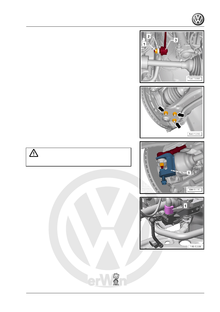
– Remove the hex nut -1- from the right and left coupling rod

-3-.

– Remove the coupling rod -3- from the stabilizer bar -2- on the

left and right sides.

– Remove the nuts -arrows- on the left and right side of the ve‐

hicle.

– Remove the control arm from the ball joint.

– Loosen the nut from the tie rod end, but do not unscrew yet.

Caution

To protect the thread, screw the nut on the pin a few turns.

– Remove the tie rod end from the wheel bearing housing and

remove the nut.

1 - -T10187-

Vehicles with Level Control System Sensor
– Disconnect the connector -1- from the Left Front Level Control

System Sensor - G78- or  Right Front Level Control Sensor -

G289- .

Continuation for all Vehicles

– Disconnect the connector -1- for the Oil Level Thermal Sensor

- G266- .

– If equipped, disconnect the connector -2- from the After-Run

Coolant Pump - V51- . To do so, open the catch -3- in the

direction of the -arrow- and release the connector.

– Remove the clips -1- and -2- for the wiring harness -3- from

the subframe and the steering gear.

– Place the -VAS6931- -1- under the subframe.
– Secure the subframe (refer to

⇒ “2.2 Subframe, Securing”, page 17

 ) and lower it approxi‐

mately 10 cm.

– Remove the bolts -arrows- and remove the heat shield -1- from

the steering gear.

Note

Different heat shields -1- are installed depending on the engine.

On some engine versions, the connectors for the steering gear

are accessible without having to remove the heat shield.

– Disconnect the connectors -1 and 2- from the steering gear.

– Unclip the wiring harness -1- from the steering gear -2-

-arrows-.

– Remove the expanding clip -arrow-.
– Lower the subframe using the -VAS6931- .

– Secure the subframe to the -VAS6931- with the accompanying

strap.

Installing
Install in reverse order of removal. Note the following:

– Tighten nuts -arrows-.

Note

Tighten the nuts -arrows- in curb weight position. Refer to

⇒ “3.8.1 Wheel Bearing in Curb Weight, Lifting Vehicles with

Coil Spring, Front Axle”, page 6

 .

Coat the seal on the steering gear with lubricant such as soft

soap before installing the steering gear.

After attaching steering gear to the universal joint, make sure

that seal on steering gear is positioned on the mounting plate

without and kinks and is sealed correctly. The opening to the

footwell must be sealed correctly. Ingress of water and/or

noises may be the result.

Make sure sealing surfaces are clean.

– For vehicles with a level control system sensor, perform the

basic setting for the wheel damping electronics using the Ve‐

hicle Diagnostic Tester.

Tightening Specifications
♦ Refer to 

⇒ “2.1 Overview - Subframe”, page 16

♦ Refer to 

⇒ “5.1 Overview - Wheel Bearing”, page 70

♦ Refer to 

⇒ “3.1 Overview - Steering Gear”, page 350

♦ Refer to 

⇒ “2.1 Overview - Steering Column”, page 338

♦ Pendulum support bolts. Refer to ⇒  Rep. Gr.  10 ; Subframe

Mount; Overview - Subframe Mount .

♦ Noise insulation bolts. Refer to ⇒  Body Exterior; Rep. Gr.  66 ;

Noise Insulation; Overview - Noise Insulation .

♦ Double clamp for exhaust pipes. Refer to ⇒  Rep. Gr.  26 ;

Exhaust Pipes/Mufflers; Overview - Muffler .

⇒ “1.1 Wheel Bolt Tightening Specifications”, page 286

If the steering wheel is still crooked after using the -T10486/1-

then an axle alignment is necessary. In this case the record it in

the vehicles axle alignment log.

2.6

Subframe, Servicing

Special tools and workshop equipment required
♦ Bearing Installer - Wheel Hub/Bearing Kit - T10205-
♦ Torque Wrench 1332 40-200Nm - VAG1332-
♦ Hydraulic Press - VAS6178-
♦ Pneumatic/Hydraulic Foot Pump - VAS6179-
♦ Hydraulic Press - Bushing Tool Kit - VAS6779-
♦ Thrust Piece - VAS6779/1-
♦ Threaded Rod - VAS6779/2-
♦ Hexagon Nut - VAS6779/3-
♦ Tube - VAS6779/4-
♦ Thrust Piece - VAS6779/5-
♦ Funnel - VAS6779/6-


Content   ..  809  810  811  812   ..