Volkswagen Golf / Golf GTI / Golf Variant. Manual - part 468


  Index      Volkswagen     Volkswagen Golf / Golf GTI / Golf Variant - service repair manual 2013 year


Search            copyright infringement  


Content   ..  466  467  468  469   ..


Volkswagen Golf / Golf GTI / Golf Variant. Manual - part 468


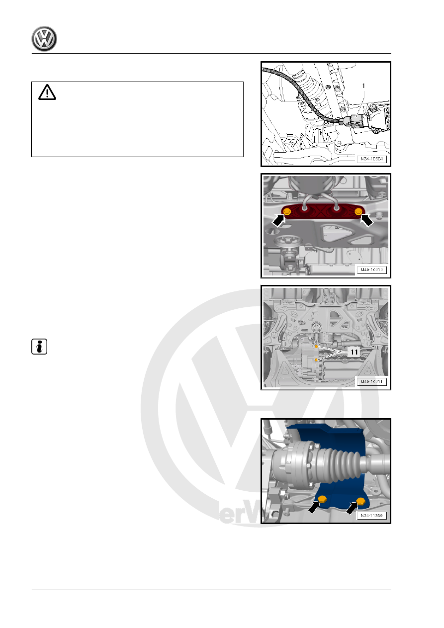
– If equipped, disconnect the connector -1- from the Oil Level

Thermal Sensor - G266- .

Caution

Risk of damaging the decoupling element.

♦ Do not bend the decoupling element more than 10°.
♦ Do not load the decoupling element.
♦ Do not damage the wire mesh on the decoupling element.

– Disconnect the exhaust system at the clamping sleeve and

remove the exhaust system bracket from the subframe

-arrows-. Refer to ⇒  Rep. Gr.  26 ; Exhaust Pipe/Muffler;

Overview - Muffler .

– Tie up the front exhaust pipe.

– Remove the bolts -11- and then remove the pendulum support

from the transmission.

– Secure the subframe before removing. Refer to ⇒  Suspen‐

sion, Wheels, Steering; Rep. Gr.  40 ; Subframe; Subframe,

Securing .

Note

If the subframe is not secured, a vehicle alignment must be per‐

formed later.

– Remove the subframe without the steering gear. Refer to ⇒ 

Suspension, Wheels, Steering; Rep. Gr.  40 ; Subframe; Sub‐

frame without Steering Gear, Removing and Installing .

– If equipped, remove the heat shield above the right driveshaft

-arrows-.

– Remove both driveshafts from the transmission. Refer to ⇒ 

Suspension, Wheels, Steering; Rep. Gr.  40 ; Driveshaft, Re‐

moving and Installing .

– Secure the driveshafts to the suspension strut using a Ten‐

sioning Strap - T10038- .

Do not damage the surface of the shafts.

– Remove the bolts -1 and 2- from the transmission bracket

-A-.

Always replace the bolts.

– Lower the engine/transmission approximately to the dimen‐

sion -a- using the spindles on the Engine Support Bridge -

10-222A- .

Dimension -a- = approximately 50 mm

– Remove the transmission bracket in direction of -arrow-.

To remove the transmission “0D9”, the Transmission Support -

3282- is equipped with the Transmission Support - Mounting Plate

- 3282/42A- and positioned on the Engine and Gearbox Jack -

VAS6931- .
– Align the arms of the Transmission Support so that they match

up with the holes in the Transmission Support - Mounting Plate

42A - 3282/42A- .

– Install the mounting element as illustrated on the Transmission

Support - Mounting Plate 42A - 3282/42 A- .

– Place the Engine and Gearbox Jack - VAS6931- under the

vehicle.

• The arrow symbol on the Transmission Support - Mounting

Plate 42A - 3282/42A- points in the direction of travel.

– Align the Transmission Support - 3282- so that it is parallel to

the transmission.

– Install the Transmission Support - Pins 29 - 3282/29- in the

transmission.

– Secure both the other support elements to the transmission as

shown.

Note

Contrary to the illustration of the Adjusting Plate , the front

support element is shown attached to the transmission with an

M10 x 50 mm bolt -arrow-. Install a M12 bolt between the

mount and the transmission housing.

DSG transmission 02E “AWD” is shown in the illustration. The

support elements on the “0D9” “FWD” transmission are iden‐

tical.

– Support the transmission by lifting it from underneath using the

Engine and Gearbox Jack - VAS6931- .

The transmission is disconnected from the engine in this position.
– Remove the remaining engine/transmission connecting bolts.
– Remove the transmission from the engine (alignment

sleeves), and »also pay attention to the selector lever cable«.

Tilt the transmission to the left by adjusting the spindle for the

Transmission Support - 3282- .

– Slightly turn and lower the transmission. Make sure that the

right flange shaft -1- is guided past when lowering the inter‐

mediate plate -arrow-.

Note

Pay attention to all of the lines when lowering the transmission.

Transmission, transporting. Refer to

⇒ “5 Transmission, Transporting”, page 100

 .

Secure the transmission on the assembly stand. Refer to

⇒ “7 Securing on Engine and Transmission Holder”, page 104

 .

Install the transmission. Refer to

⇒ “3.2 Transmission, Installing”, page 91

 .

3.2

Transmission, Installing

Caution

This procedure contains mandatory replaceable parts. Refer

to component overview prior to starting procedure.

Mandatory Replacement Parts
♦ Bolts - Engine to Transmission Connecting
♦ Bolts - Subframe Mount
♦ Lockwashers - Selector Mechanism Cable
Install in reverse order of removal. Note the following:

Note

Refer to “Transmission, Removing”

⇒ “3.1 Transmission, Removing”, page 72

 for a list of the spe‐

cial tools needed.

After installing a »new« transmission, reprogram the immobil‐

izer.

Note

Always replace the needle bearing -arrow- after separating the

engine and transmission.

If the needle bearing in the crankshaft is damaged, the gears

will no longer shift correctly.

– Replace the needle bearing in the crankshaft. Refer to ⇒  Rep.

Gr.  13 ; Crankshaft; Needle Bearing in Crankshaft, Replacing .

– Transmission pins (not splines) must also be lightly lubricated.
– Make sure both alignment sleeves between the engine and

the transmission are correctly seated.

– Make sure the intermediate plate fits correctly.


Content   ..  466  467  468  469   ..