Volkswagen Golf / Golf GTI / Jetta. Manual - part 556
 

  Index      Volkswagen     Volkswagen Golf / Golf GTI / Jetta - service repair manual 1999-2005 year


Search            copyright infringement  


Content   ..  554  555  556  557   ..


Volkswagen Golf / Golf GTI / Jetta. Manual - part 556


- Remove spring 

Removing spring 


42-4, Spring, removing and installing

 . 

Removing spring R32 


42-4, Spring R32, removing and 

installing

 . 

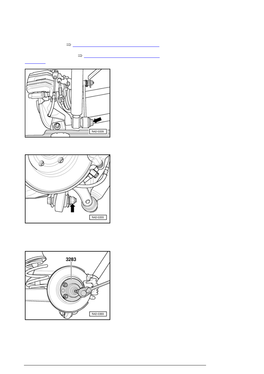
- Remove lower bolt - arrow - from shock absorbers. 

- Disconnect transverse link at trailing arm - arrow - 

- Loosen transverse link connection bolt on subframe. 

- Press out drive axle. 

Note

Trailing arm and transverse links (all-wheel drive vehicles), assembly overview


n

When pressing drive axle out ensure there is sufficient 
clearance.  


- Pull down trailing arm from control arm. 

- Install tools as shown in illustration. 

Make sure when setting the tools that the recess  - arrow - 
of the press piece T10254/2 - 3 - is correctly positioned. 

1. Nut T10254/4 with Spindle T10254/5  
2. Thrust piece T10030/1A  
3. Press piece T10254/2  
4. Hydraulic press VAS 6178  

- Pull ball joint out 

Install lower bonded rubber bushing


Trailing arm and transverse links (all-wheel drive vehicles), assembly overview


- Install tools as shown in illustration. 

Make sure when setting the tools that the recess is on the 
milled side T10254/3 - arrow - of the press piece T10254/2 
- 4 - is correctly positioned. 

1. Nut T10254/4 with Spindle T10254/5  
2. Press piece T10254/1  
3. Bonded rubber bushing  
4. Press piece T10254/3  
5. Hydraulic press VAS 6178  

Make sure there is sufficient space when tightening.

- Draw in rubber mounted bushing. 

- Secure lower control arm at trailing arm with new nut and 
bolt. 

- Install shock absorber to trailing arm 

- Installing spring: 

Installing spring 


42-4, Spring, removing and installing

 . 

Installing spring R32 


42-4, Spring R32, removing and 

installing

 . 

Trailing arm and transverse links (all-wheel drive vehicles), assembly overview


Tightening bearing bracket is only possible from below, 
when the measured value - a - from the middle of wheel 
hub to lower edge bordering wheel housing is reached. 

- Turn wheel hub until one of the holes for the wheel bolts is 
at the 12 o'clock position. 

- Install wheel hub support T10149 with a wheel bolt. 

- Raise wheel bearing housing using engine/transmission 
jack until dimension - a - is reached. 

Caution!  

n

Do not raise or lower the vehicle if the 
engine/transmission jack is under the vehicle.  


n

Do not leave engine/transmission jack under the 
vehicle longer than necessary.  


- Tighten bolts from bearing bracket to rear axle with 
tightening torque. 

Fastener/location

Tightening torques

Transverse link to trailing arm  
Use new nuts and bolts! 

70 Nm plus an additional 

1

 / 

4

 turn 90   

Shock absorber to trailing arm 

110 Nm

12-point nut to wheel hub 


42-7, Installing


Trailing arm, removing and installing 

Special tools, testers and auxiliary items required 

Trailing arm and transverse links (all-wheel drive vehicles), assembly overview


Content   ..  554  555  556  557   ..