Volkswagen Golf / Golf GTI / Jetta. Manual - part 483
 

  Index      Volkswagen     Volkswagen Golf / Golf GTI / Jetta - service repair manual 1999-2005 year


Search            copyright infringement  


Content   ..  481  482  483  484   ..


Volkswagen Golf / Golf GTI / Jetta. Manual - part 483


47-74


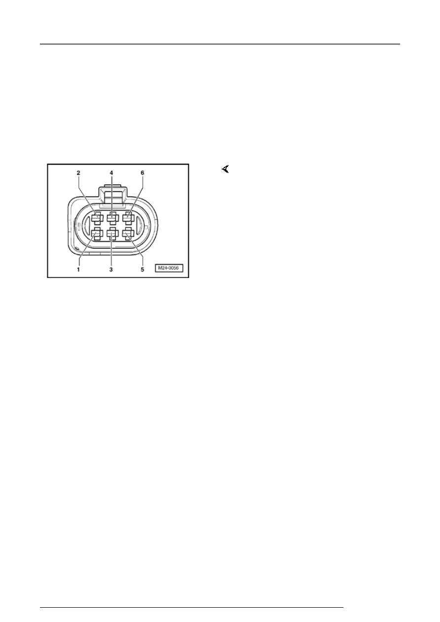
Multi-pin connector with 
contact assignment 


Note:  


All contacts not listed are currently 
not assigned and must never be 
connected to other components!
 

     Contact assignment of 

connectors for voltage supply and 
diagnosis. 
 

Contact 
1  

=   Ground  

Contact 
2  

=   Connection with 

engine control module 
(pin 22)   

Contact 
3  

=   Not applicable  

Contact 
4  

=   Not applicable  

Contact 
5  

=   Voltage supply from 

Battery + through fuse 
51  

Contact 
6  

=   Not applicable  

Brake booster/brake master cylinder for vehicles with ABS/EDL/ASR/ESP Mark...

47-75


Contact  

Wiring connection to component ...  

1  

   Ground point  

2  

   Connection with engine control module  

3  

   Not applicable  

4  

   Not applicable  

5  

   Voltage supply from Battery +  

6  

   Not applicable  

Brake booster/brake master cylinder for vehicles with ABS/EDL/ASR/ESP Mark...

47-76


Test step overview  

To test component  


Resistance of -V192- brake system vacuum pump  

- Perform test 
step 1 

Communication signal of engine control unit to -V192- brake 
system vacuum pump  

- Perform test 
step 2 

Resistance of connection of battery to -V192- brake system 
vacuum pump  

- Perform test 
step 3 

Voltage supply of Battery to -V192- brake system vacuum pump  

- Perform test 
step 4 

Brake booster/brake master cylinder for vehicles with ABS/EDL/ASR/ESP Mark...

47-77


Test table (test steps 1 - 4) 


Notes on test table  

 The socket designations of adapter VAG 1598/31 (for test step 2) are identical to the 

engine control module contact designations in wiring diagram.  

 Electrical Wiring Diagrams, Troubleshooting & Component Locations binder  

 If the readings obtained deviate from the specifications, carry out repair measure in 

the right-hand part of the table.  

 Electrical Wiring Diagrams, Troubleshooting & Component Locations binder  

 If the measured figures deviate slightly from the specifications, clean sockets and 

plugs of the testers and adapter cables (with contact spray G 000 700 04) and repeat 
check. Before replacing components, check wiring and connections and also, 
particularly for specifications of less than 10 

, repeat resistance check on the 

component. 

Brake booster/brake master cylinder for vehicles with ABS/EDL/ASR/ESP Mark...


Content   ..  481  482  483  484   ..