Volkswagen Golf / Golf GTI / Jetta. Manual - part 418
 

  Index      Volkswagen     Volkswagen Golf / Golf GTI / Jetta - service repair manual 1999-2005 year


Search            copyright infringement  


Content   ..  416  417  418  419   ..


Volkswagen Golf / Golf GTI / Jetta. Manual - part 418


45-56


Location: 


The control module is bolted to the hydraulic unit 
and is located on left in the engine compartment. 


WARNING!


Do not bend the brake lines in the area of the 
hydraulic unit!


Removing:  


-  Request radio code on vehicles with coded radio 

if necessary. 


-  Disconnect battery. 


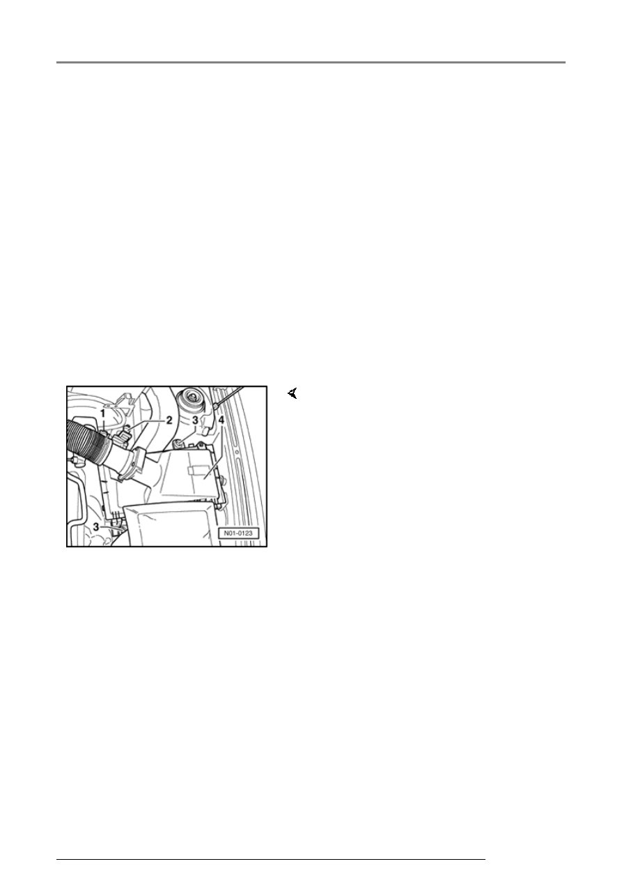
Remove air cleaner  


-  Pull connector -2- off mass air flow sensor.

-  Release spring-type clip -1- on air duct hose 

with pliers VAG 1921 and pull hose off air 
cleaner. 

-  Remove air cleaner bolts -3- and take out air 

cleaner -4-. 

Hydraulic unit, brake booster/brake master cylinder Mark 60, assembly overview

45-57


-  Release control module 

connector (arrow -1-) and pull off 
(arrow -2-). 

-  Install brake pedal loading device 

VAG 1869/2. 

-  Connect bleeder bottle hose to 

left front brake caliper and left 
rear caliper bleed screw and open 
bleed screws. 

-  Depress brake pedal at least 60 

mm. (2.36 in.) with brake pedal 
depressor VAG 1869/2. 

Hydraulic unit, brake booster/brake master cylinder Mark 60, assembly overview

45-58


-  Close left front and left rear caliper bleeder 

screws. 


-  Do not remove brake pedal depressor VAG 

1869/2 from brake pedal. 


-  Place sufficient lint-free cloths under the control 

module and hydraulic unit. 


Make sure no brake fluid gets on contacts.


-  Disconnect brake lines -1- from hydraulic unit to 

brake master cylinder and tie up 

-  Disconnect remaining brake lines on hydraulic 

unit. 

-  Seal brake lines and threaded holes with plugs 

from repair kit Part No. 1H0 698 311 A. 

-  Remove bolts (arrows) from hydraulic 

unit/control module bracket. 

-  Remove hydraulic unit with control module.

Hydraulic unit, brake booster/brake master cylinder Mark 60, assembly overview

45-59


Removing control module from hydraulic 
unit. 


-  Place the hydraulic unit with control module 

down on a clean flat surface. 


CAUTION!


The hydraulic pump must not be separated 
from the hydraulic unit.


-  Remove E 5 hex socket head bolt -arrows

hydraulic pump. 


-  For this reason, tighten the hydraulic pump with 

the red bracket -1- from the repair kit and two 
sealing plugs -2- on the hydraulic unit. 

Hydraulic unit, brake booster/brake master cylinder Mark 60, assembly overview


Content   ..  416  417  418  419   ..