Volkswagen Golf / Golf GTI / Jetta. Manual - part 355
 

  Index      Volkswagen     Volkswagen Golf / Golf GTI / Jetta - service repair manual 1999-2005 year


Search            copyright infringement  


Content   ..  353  354  355  356   ..


Volkswagen Golf / Golf GTI / Jetta. Manual - part 355


01-104


Test requirements  


 Switch ignition and electrical 

consumers off before beginning 
the check (headlights, lighting, 
fan ...). 


 Fuses S9, S13, S178 and S179 

must be OK (remove fuses from 
fuse holder to check). 


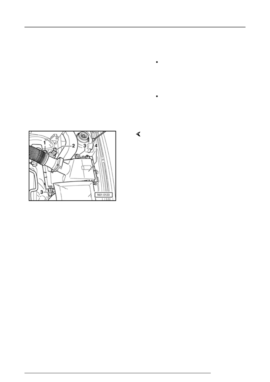
Removing air cleaner  


-  Pull connector -2- off mass air 

flow sensor. 

-  Release spring-type clip -1- on air 

duct hose with pliers V.A.G 1921 
and pull hose off air cleaner. 

-  Remove air cleaner bolts -3- and 

take out air cleaner -4-. 

ABS, ABS/EDL and ABS/EDL/ASR ITT Mark 20 IE, electrical check

01-105


-  Release ABS control module 

(w/EDL) -J104- connector -arrow 
1- and pull off -arrow 2-. 


The specified values are matched to 
the V.A.G 1526 and are not 
necessarily applicable for other test 
units.  

-  Connect test box V.A.G 1598/21 -

1- to multi-pin connector of ABS 
control module (w/EDL) -J104- (-
2-). 

ABS, ABS/EDL and ABS/EDL/ASR ITT Mark 20 IE, electrical check

01-106


Multi-pin connector with 
contact assignment 


Note:  


All contacts not listed are currently 
not assigned and must never be 
connected to other components!
 

     Contact assignment of 

connectors for voltage supply and 
On Board Diagnostic (OBD) with 
V.A.G 1551 Scan Tool 
 

Contact 
4  

=   Ground (terminal 31)  

Contact 
16  

=   Positive (terminal 30) 

to S12  

Contact 
7  

=   K wire to contact 7 of 

multi-pin connector 
T25 of ABS control 
module (w/EDL) -
J104-  

     Contact assignment of connector 

T25 wiring harness/ABS control 
module (w/EDL) -J104- 
 

ABS, ABS/EDL and ABS/EDL/ASR ITT Mark 20 IE, electrical check

01-107


Contact  

Wiring connection to component ...  

1  

   Left front ABS wheel speed sensor -G47-  

2  

   Left front ABS wheel speed sensor -G47-  

3  


Coding bridge to contact 14  

4  

   Voltage supply to ignition switch  

5  

   Left rear ABS wheel speed sensor -G46-  

6  

   Left rear ABS wheel speed sensor -G46-  

7  

   Connector T16/7, K wire  

8  

   Ground point left in engine compartment and Ground connection in 

engine compartment wiring harness  

9  

   Voltage supply from battery +  

10  

   Data bus wire 

 Wiring diagrams  

11  

   Data bus wire 

 Wiring diagrams  

12  


Vehicles with navigation system only  

ABS, ABS/EDL and ABS/EDL/ASR ITT Mark 20 IE, electrical check


Content   ..  353  354  355  356   ..