Volkswagen Golf / Golf GTI / Jetta. Manual - part 237
 

  Index      Volkswagen     Volkswagen Golf / Golf GTI / Jetta - service repair manual 1999-2005 year


Search            copyright infringement  


Content   ..  235  236  237  238   ..


Volkswagen Golf / Golf GTI / Jetta. Manual - part 237


24-202


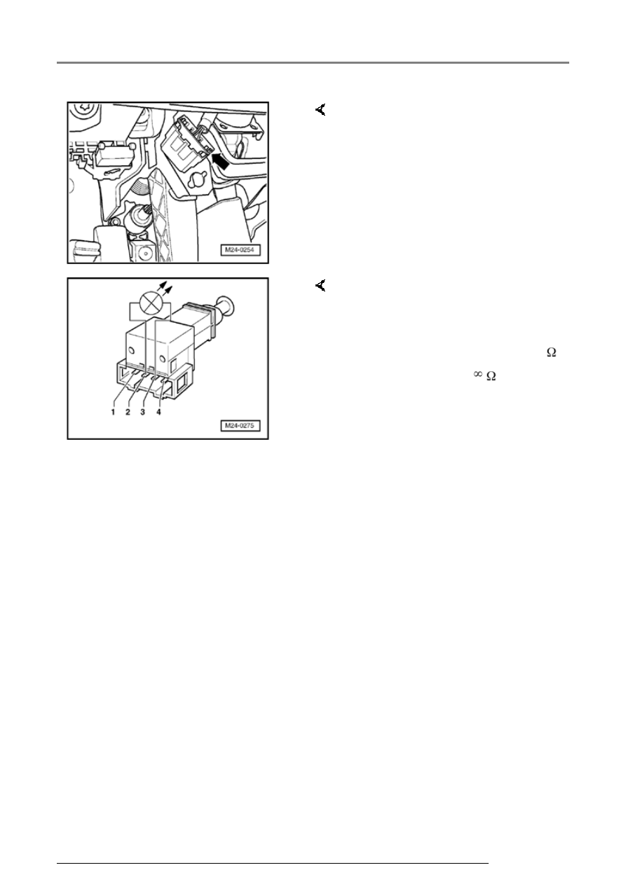
-  Disconnect 4-pin connector from 

Clutch Vacuum Vent Valve Switch 
-F36- (arrow). 


If the specifications are not 
obtained:  

Note:  

Observe installation position of 
Clutch Vacuum Vent Valve Switch -
F36- through upper assembly hole of 
bearing bracket.
 

-  Measure resistance between 

switch terminals 2 and 3. 

   Specification: 

   Clutch not depressed: max. 1.5 


   Clutch depressed: 


-  Replace Clutch Vacuum Vent 

Valve Switch -F36-. 

Additional signals, checking

24-203


-  Check DTC memory, repair malfunctions if 

necessary and then erase DTC memory 

01-23

 . 


-  Read readiness code 


Page 01-146

 . If DTC 

memory has been erased or Motronic Engine 
Control Module (ECM) -J220- was disconnected 
from battery positive (B+), readiness code must 
be generated again 


Page 01-149

 . 


If the specifications are obtained:  


If the specification is not obtained:  

-  Connect multimeter to measure voltage at 

connector terminal 2 and engine Ground (GND).

-  Switch ignition on. 

   Specification: at least 11.5 V 

-  Switch ignition off. 

-  Check wire for open circuit between 4-pin 

connector terminal 2 and Fuel Pump (FP) Relay 
-J17- referring to Electrical Wiring Diagrams.

   Wire resistance: max. 1.5 


Additional signals, checking

24-204


If the specification is obtained:  


-  Remove wiper arms and cowl 

panel: 


Repair Manual, Electrical 

Equipment; Repair Group 92


-  Connect VAG 1598/31 test box to 

control module wiring harness. 
Engine Control Module (ECM) -
J220- remains disconnected. 


-  Check wiring for open circuit 

between test box and 4-pin 
connector referring to Electrical 
Wiring Diagrams. 

   Terminal 3 and socket 39 

   Wire resistance: max. 1.5 


-  Additionally check wiring for short 

to one another, to vehicle Ground
(GND) and to battery positive. 

   Specification: 


Additional signals, checking

24-205


   If there is no Diagnostic Trouble Code (DTC) in 

the wiring and the resistance measurement 
values are OK.:  


-  Replace Motronic Engine Control Module (ECM) 

-J220- 


Page 24-173

 . 


-  Check DTC memory, repair malfunctions if 

necessary and then erase DTC memory 


Page 

01-23

 . 


-  Erase learned values and adapt Motronic 

Engine Control Module (ECM) -J220- again 


Page 24-182

 . 


-  Read readiness code 


Page 01-146

 . If DTC 

memory has been erased or Motronic Engine 
Control Module (ECM) -J220- was disconnected 
from battery positive (B+), readiness code must 
be generated again 


Page 01-149

 . 

Additional signals, checking


Content   ..  235  236  237  238   ..