Volkswagen Golf / Golf GTI / Jetta. Manual - part 199
 

  Index      Volkswagen     Volkswagen Golf / Golf GTI / Jetta - service repair manual 1999-2005 year


Search            copyright infringement  


Content   ..  197  198  199  200   ..


Volkswagen Golf / Golf GTI / Jetta. Manual - part 199


24-50


Checking voltage supply  


If no voltage is present:  


Repair Manual, Electrical 

Equipment; Repair Group 92


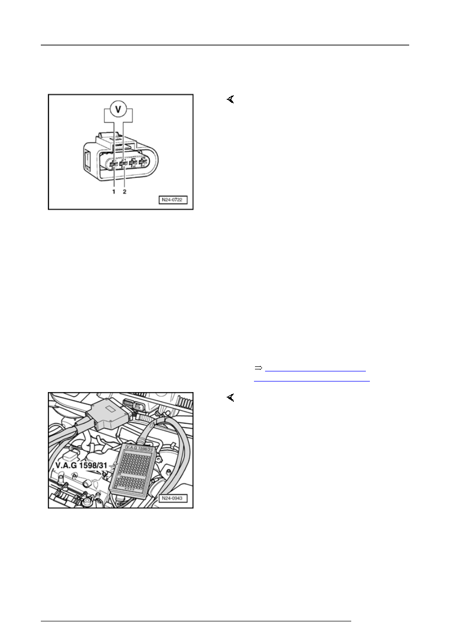
-  Connect multimeter to measure 

voltage at terminals 1 and 2 
(connector to Motronic Engine 
Control Module (ECM) -J220-) 
using adapter cables from VAG 
1594. 

-  Start engine and run at idle 

speed. 

-  Measure voltage supply and 

observe display group 41, display 
zone 4. 

-  Display Htg.aC.ON: Specification: 

11.0 to 14.5 V 

   Display Htg.aC.ON / Htg.aC.OFF 

(alternating): Specification: 
Between 0.0 to 12.0 V fluctuating 

-  Switch off ignition. 

-  Remove wiper arms and cowl 

panel: 


-  Connect VAG 1598/31 test box to 

control module wiring harness. 
Engine Control Module (ECM) -
J220- remains disconnected. 

Components, checking

24-51


If the specification is obtained:  

If no wiring malfunction is detected:  

-  Check wiring for open circuit 

between test box and 4-pin 
connector referring to Electrical 
Wiring Diagrams. 

   Terminal 2 and socket 63 

   Wire resistance: max. 1.5 


-  Check wire for open circuit 

between 4-pin connector terminal 
1 and Fuel Pump (FP) relay -J17- 
referring to Electrical Wiring 
Diagrams. 

   Wire resistance: max. 1.5 


-  Replace Motronic Engine Control 

Module (ECM) -J220- 


Page 24-

173

 . 

-  Check DTC memory, repair 

malfunctions if necessary and 
then erase DTC memory 


Page 

01-23

 . 

-  Erase learned values and adapt 

Motronic Engine Control Module 
(ECM) -J220- again 


Page 24-

182

 . 

-  Read readiness code 


Page 01-

146

 . If DTC memory has been 

erased or Motronic Engine 
Control Module (ECM) -J220- was 
disconnected from battery 
positive (B+), readiness code 
must be generated again 


Page 

01-149

 . 

Components, checking

24-52


Mass Air Flow (MAF) sensor -
G70- , checking


Note:  


Only gold plated terminals may be 
used to service terminals in the 
Mass Air Flow (MAF) sensor 
connector.


Special tools, materials and 
equipment 


Note:  

All functions which could previously 
be performed with VAG 1551/1552 
can also be performed with the VAS 
5051.
 

 VAG 1551 Scan tool (or VAG 

1552) with VAG 1551/3 adapter 
cable 

 VAG 1526 or Fluke 83 Hand 

multimeter or VAG 1715 
multimeter 

 VAG 1594 Adapter set 

 VAG 1598/31 Test box 

 Electrical Wiring Diagrams 

Components, checking

24-53


Test requirements  


 Electrical Wiring Diagrams, 

Troubleshooting & Component 
Locations
 

 The fuses must be OK. 

 The battery voltage must be at 

least 11.5 V. 

 All electrical accessories, e.g. 

lights and rear window defroster 
must be switched off. 

 If the vehicle is equipped with air 

conditioning, it must be turned 
off. 

 Selector lever must be in 

position "P" or "N" on vehicles 
with an automatic transmission. 

 Fuel Pump (FP) -J17- must be 

OK., checking: 

 Coolant temperature must be at 

least 85  C, 

display group 1, 

display zone 2. 

Components, checking


Content   ..  197  198  199  200   ..