Volkswagen Golf / Golf GTI / Jetta. Manual - part 1061


  Index      Volkswagen     Volkswagen Golf / Golf GTI / Jetta - service repair manual 1999-2005 year


Search            copyright infringement  


Content   ..  1059  1060  1061  1062   ..


Volkswagen Golf / Golf GTI / Jetta. Manual - part 1061


01-152


Notes:  


 Interpreting display groups and evaluating 

measured values in individual display fields 

tables beginning 


Page 01-153

 . 


 With the printer switched on, the information on 

the display is printed out. 


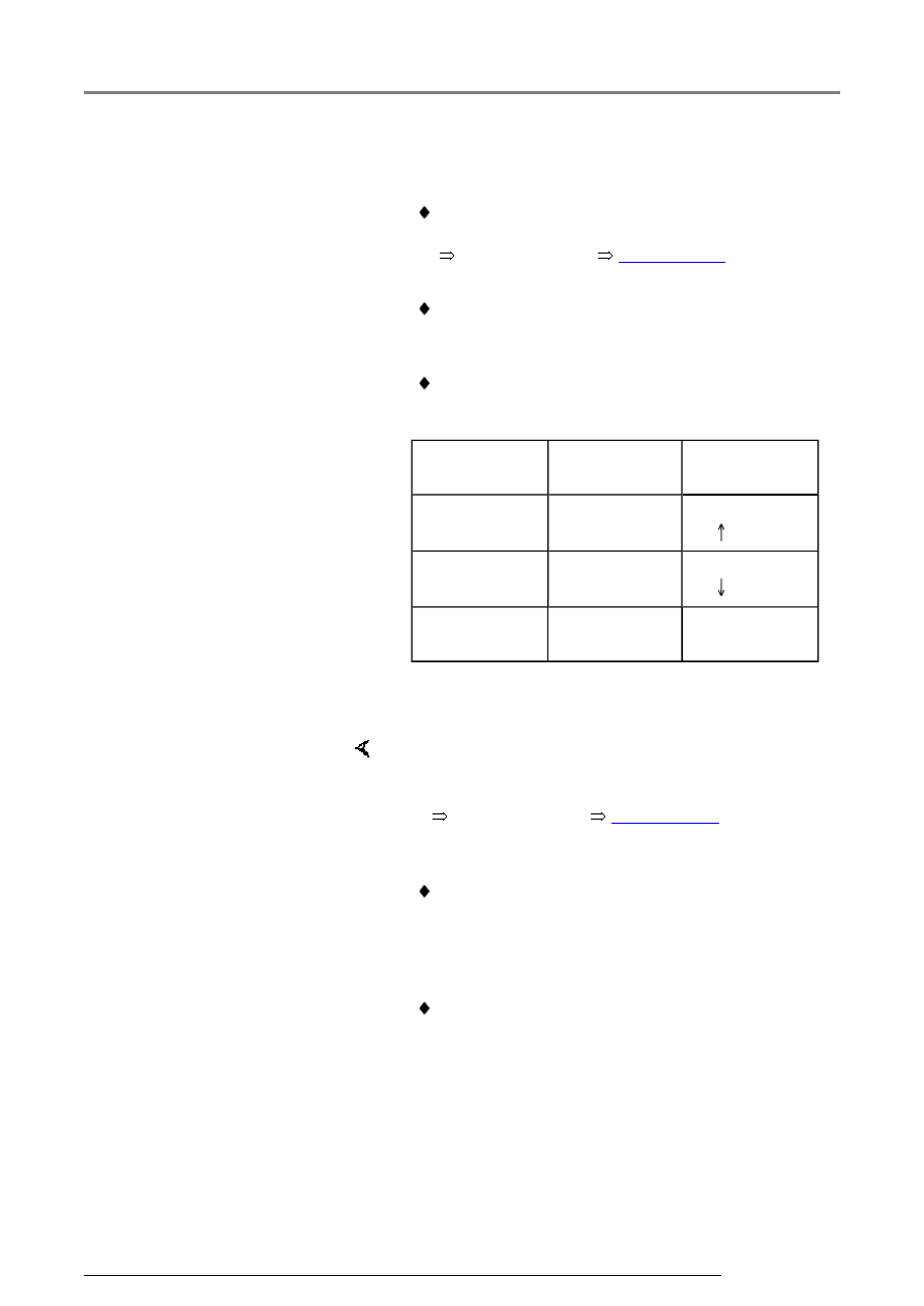
 To easily change between display groups, 

proceed as follows: 


Display 
group 
 

VAG 1551  

VAG 1552  

Higher  

Press button 

3  

Press 

button  

Lower  

Press button 

1  

Press 

button  

Skip  

Press button 

C  

Press button 

C  


-  Displayed after pressing C button. 

Read Measuring Value Block HELP

Enter display group number XXX

     Indicated on display:  

Notes: 

-  Enter alternate display group number as needed 

tables beginning 


Page 01-153

 . 

 Display fields always show actual values 

transmitted from senders and sensors. 
However, instrument cluster display values can 
differ from those in the display fields due to 
internal filtering.
 

 Other display groups are possible, but are not 

required for On Board Diagnostic program! 

Data Bus On Board Diagnostic Interface -J533- ('Gateway') m.y. 2000 through m...

13/2/2005

01-153


   Notes:  


 Display fields in display groups 125 and 126 

provides the CAN-Bus function status codes of 
various control modules connected to the 
"Powertrain" CAN-Bus network.


 If a vehicle is not equipped with control module

(s) listed in the following display groups, the 
applicable display field remains blank. Check 
correct coding of CAN-Bus On Board 
Diagnostic (OBD) interface -J533- 


Page 01-

149

 . 


 Display field content differs between VDO and 

MMO instrument clusters! 

Display groups, interpreting  

Display group 125  

Read Measuring Value 
Block 125  


 Indicated on 

display  


xxx  

xxx  

xxx  

xxx     


1  

2  

3  

4  

 Display fields  

Designation   Evaluating display 

fields  


Airbag-control 
module

1)


Airbag 1

1)


Page 01-154


ABS control module  

ABS 1  


Autom. transmission control 
module   

Transm. 1     


Engine  

Engine 1  


1)

 Only for VDO. Motometer 

Display group 126, display field 2. 


Data Bus On Board Diagnostic Interface -J533- ('Gateway') m.y. 2000 through m...

13/2/2005

01-154


Evaluating display group 125  

Display 

field  

Description  

Display  

Corrective action  

1  

Engine Control 
Module (ECM)  

Engine 1 = 
OK,  

Data reception 
via CAN Bus 
OK  

Engine 0 = not 
OK,  

Data reception 
via CAN Bus 
not OK  

- Visually check CAN Bus wire routing 

- Check harness connectors of the 
appropriate electrical circuit for proper 
and secure seating and 
simultaneously observe display 

- If the display content does not 
change during operation, repair 
malfunction 

- Erase DTC memory 

- Perform functional check 

- Check DTC memory again 

2  

Transmission 
Control Module 
(TCM)  

Transm. 1 = 
OK,  

Data reception 
via CAN Bus 
OK  

Transm. 0 = 
not OK,  

Data reception 
via CAN Bus 
not OK  


3  

ABS-control 
module  

ABS 1 = OK,  

Data reception 
via CAN Bus 
is OK  

ABS 0 = not 
OK,   

Data reception 
via CAN Bus 
not OK  


4  

Airbag-control 
module  

Airbag 1 = 
OK,  


Data Bus On Board Diagnostic Interface -J533- ('Gateway') m.y. 2000 through m...

13/2/2005

Data reception 
via CAN Bus 
is OK  

Airbag 0 = not 
OK,  

Data reception 
via CAN Bus 
not OK  

Data Bus On Board Diagnostic Interface -J533- ('Gateway') m.y. 2000 through m...

13/2/2005


Content   ..  1059  1060  1061  1062   ..