Volkswagen Jetta / Bora: Electrical System Manual - part 76
 

  Index      Volkswagen     Volkswagen Jetta (2005 year) / Bora (2006 year) - Electrical System manual


Search            copyright infringement  


Content   ..  74  75  76  77   ..


Volkswagen Jetta / Bora: Electrical System Manual - part 76


Final control diagnosis trailer detector

control unit -J345-

Note

The trailer detector control unit -J345- detects from a power

draw of minimum 5 W 

4)

 the “trailer operation”.

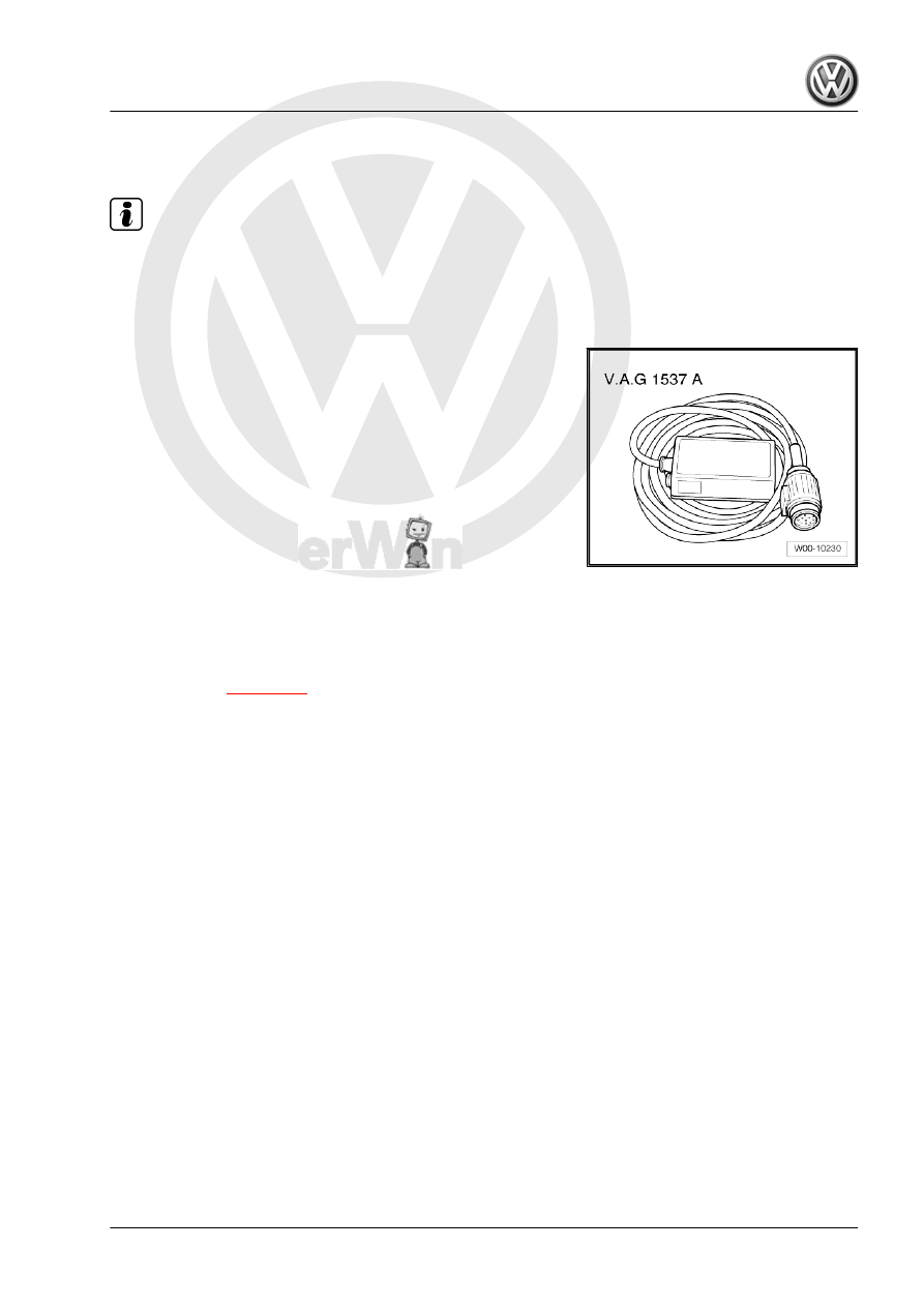
To check use plug socket tester -V.A.G 1537/A- .

Special tools and workshop equipment required
♦ Plug socket tester -V.A.G 1537/A- 

5)

5) After a few minutes the plug socket tester -V.A.G 1537/A- gets to hot and

switches off automatically. After a cooling period the plug socket tester -V.A.G

1537/A- works again perfectly.

– Connect the plug socket tester -V.A.G 1537/A- .
– Connect Vehicle Diagnosis, Testing and Information System

-VAS 5051A- 

⇒ page 281

 .

– Select “guided fault finding” in Vehicle Diagnosis, Testing and

Information System -VAS 5051A- .

– Using the “Go to” key, select “Function/component selection”

and the following menu items one after the other:

♦ Body
♦ General Body Repairs
♦ 01 - On Board Diagnostic capable systems
♦ Trailer detector
♦ Function
♦ Trailer detector control unit - Final control diagnosis

Jetta 2005 ➤ , Bora 2006 ➤

5. Control units    

301

Wiring harness and connector re‐

pairs

6.1

Safety instructions

Caution

For repair work on airbag and seat belt tensioner wiring har‐

nesses, only contacts, connectors and wiring designed specif‐

ically for this purpose may be used ⇒  Parts catalogue (ETKA)!

♦ Observe country-specific regulations.
♦ Observe vehicle stickers indicating high voltage components.

Before carrying out repairs, discharge residual voltage.

♦ Wires from airbag and belt tensioner wiring harness must only

be repaired using wiring harness repair set -V.A.G 1978- .

⇒  Operating instructions wiring harness repair set -V.A.G 1978-
⇒  General body repairs interior; Rep. Gr.  69

6.2

General notes concerning repairs to ve‐

hicle electrical system

Caution

Disconnecting and connecting the battery as described in the

Workshop Manual 

⇒ page 29

 .

♦ Observe current notes (also notes concerning removing and

installing components) in workshop manuals and in the Tech‐

nical Service Handbook.

♦ Yellow wiring and sections of wiring harness wrapped in yellow

tape indicate a prior repair.

⇒  Operating instructions wiring harness repair set -V.A.G 1978-
♦ Before beginning repairs to a wiring harness, first rectify the

cause of the damage, e.g. sharp edges on a body part, de‐

fective electrical consumer, corrosion.

♦ Disconnecting the battery earth strap (open circuit) provides a

safe working environment for repairs to the electrical system.

The battery positive wire need only be disconnected for re‐

moval of the battery.

♦ If possible, do not loosen any earth wires from the body (dan‐

ger of corrosion).

6.3

Notes on repairs to wiring harness and

connectors

Supplementary notes on repair of CAN bus wiring 

⇒ page 303

♦ Soldering is not permitted for repairs to vehicle wiring.
♦ Never repair any heat-shrink connections. If necessary, lay

wiring parallel to the defective wiring.

♦ Onboard supply wiring harnesses and connectors may only

be repaired using wiring harness repair set -V.A.G 1978- .

Jetta 2005 ➤ , Bora 2006 ➤

302

repair locations with yellow tape.

♦ Shielded wires must not be repaired. In case of damage, they

must be entirely replaced.

6.4

Supplementary notes on repair of CAN

bus wiring

♦ An unshielded two-wire line -1- and -2- with a cross section of

0.35 mm

2

 or 0.5 mm

2

 is used for CAN bus wiring.

♦ The colour codes of the CAN bus wiring can be gleaned from

the following table:

Drivetrain CAN, high

orange/black

Convenience CAN, high

orange/green

Infotainment CAN, high

orange/violet

CAN Low wire (all)

orange/brown

♦ Perform wiring harness repairs only with yellow wires. Mark

repair locations with yellow tape.

♦ When repairs are performed, both bus wires must have the

same length. When wires -1- and -2- are twisted together, the

twist spacing should be A=20 mm.

♦ No section of wiring greater than B=50 mm, e.g. in the vicinity

of heat-shrink sleeves -arrow-, should not be twisted.

Jetta 2005 ➤ , Bora 2006 ➤

6. Wiring harness and connector repairs    

303

Wiring harness repair set -V.A.G 1978-

- Repairs to wiring harnesses

and connectors of the onboard

electrical supply system

should only be carried out us‐

ing wiring harness repair set -

V.A.G 1978- .
- Included with the wiring har‐

ness repair set -V.A.G 1978- is

a set of operating instructions,

which provides comprehen‐

sive information on how to con‐

duct repairs.
- Further information, e.g. re‐

moval and installation of parts

and components, appears in

the relevant workshop manual.

Jetta 2005 ➤ , Bora 2006 ➤

304


Content   ..  74  75  76  77   ..