Volkswagen Jetta / Bora: Electrical System Manual - part 72
 

  Index      Volkswagen     Volkswagen Jetta (2005 year) / Bora (2006 year) - Electrical System manual


Search            copyright infringement  


Content   ..  70  71  72  73   ..


Volkswagen Jetta / Bora: Electrical System Manual - part 72


Removing and installing relay carrier

3.1

Removing and installing relay carrier

with safety cut-out on left of dash panel

Caution

Disconnecting and connecting the battery as described in the

Workshop Manual 

⇒ page 29

 .

Removing:
– Disconnect the battery 

⇒ page 29

 .

– Remove storage compartment on driver side ⇒  General body

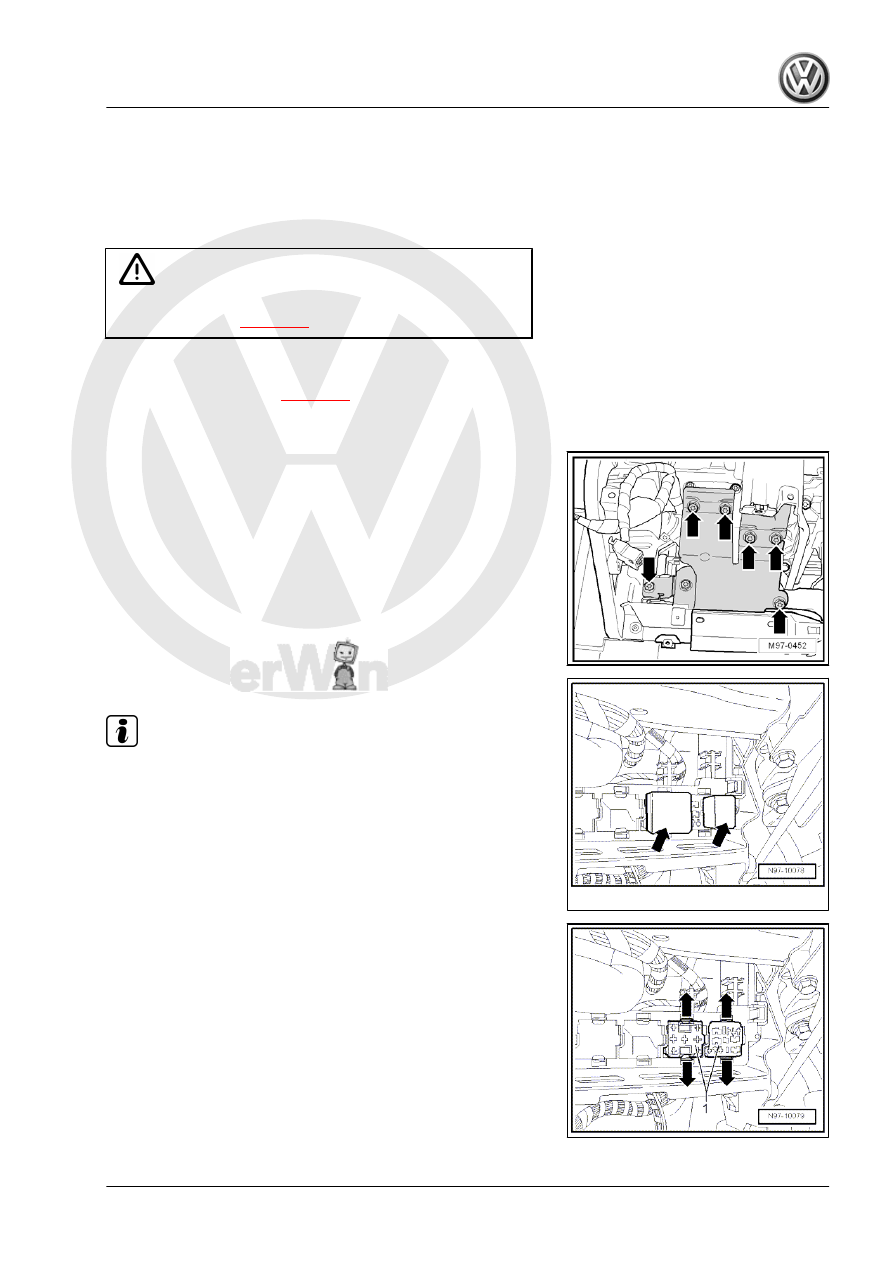
– Unscrew bolts -arrows- of the bracket.

– Pull relays -arrows- out of the relay carrier.

Note

The relay number depends on vehicle equipment.

– Clip locking lugs in -direction of arrow- outwards and then

press the connector -1- through the relay carrier.

Jetta 2005 ➤ , Bora 2006 ➤

3. Removing and installing relay carrier    

285

take relay carrier off.

Installing:
Installation is performed in the reverse order of installation; when

doing this, note the following:
– Clip connectors into the relay carrier first.

– Fit relay carrier -2- into guide -1- and engage relay carrier.

3.2

Removing and installing relay carrier on

onboard supply control unit, on left of

dash panel

Note

The onboard supply control unit -J519- and the relay carrier

attached to the onboard supply control unit, on left of dash

panel form one unit and cannot be separated.

If the onboard supply control unit -J519- is to be replaced, first

carry out the procedure

⇒ “5.1.2 Coding onboard supply control unit J519 ”,

page 293

 to read out the stored codes.

Removing:
– Switch off ignition and all electrical consumers and pull out

ignition key.

– Remove cover, footwell, on driver side ⇒  General body re‐

– Remove storage compartment on driver side ⇒  General body

Jetta 2005 ➤ , Bora 2006 ➤

286

supply control unit, on left of dash panel in

-direction of arrow A-.

– Move locking bar -2- of the connectors of the on onboard sup‐

ply control unit -J519- in -direction of arrow B-.

Note

The connectors of the onboard supply control unit -J519- and the

relay carrier on onboard supply control unit, on left of dash panel

may only be pulled off if the locking bar is set to position “OPEN”.

– Remove all connectors of the onboard supply control unit -

J519- and the relay carrier on onboard supply control unit, on

left of dash panel.

Note

The connector number depends on vehicle equipment.

– Unclip onboard supply control unit -J519- and relay carrier on

onboard supply control unit, on left of dash panel out of the

locking device -arrows C-.

– Pull onboard supply control unit -J519- and relay carrier on

onboard supply control unit, on left of dash panel downwards

and in opposite direction of travel out of the bracket.

Installing:
Installation is performed in the reverse order of installation; when

doing this, note the following:

Note

The locking bars may only be set to “CLOSE” when all connectors

are fitted “correctly”.

Jetta 2005 ➤ , Bora 2006 ➤

3. Removing and installing relay carrier    

287

Electronics boxes

4.1

Removing and installing electronics box

on left in engine compartment

Caution

Disconnecting and connecting the battery as described in the

Workshop Manual 

⇒ page 29

 .

Removing:
– Disconnect the battery 

⇒ page 29

 .

– Release clips -1- in -direction of arrow- and take cover of elec‐

tronics box -2- off upwards.

– Remove hexagon nuts -1-.
– Open -arrows- covers -2- of cable guides on electronics box.
– Remove wiring from stud connections.
– Unclip wiring from cable guides.

Jetta 2005 ➤ , Bora 2006 ➤

288


Content   ..  70  71  72  73   ..