Volkswagen Jetta / Bora: Electrical System Manual - part 50
 

  Index      Volkswagen     Volkswagen Jetta (2005 year) / Bora (2006 year) - Electrical System manual


Search            copyright infringement  


Content   ..  48  49  50  51   ..


Volkswagen Jetta / Bora: Electrical System Manual - part 50


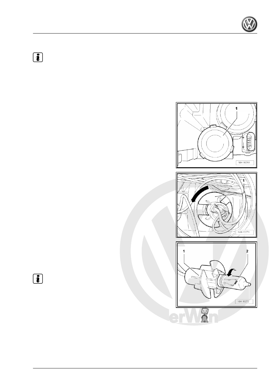
Renewing front turn signal bulb

Note

The following diagrams show renewal of the turn signal bulb for

the left headlight.

Removing:
– Switch off ignition and all electrical consumers and pull out

ignition key.

– Pull off cover cap -1-.

– Pull, depending on the cable length, the bulb holder -1- with

the front turn signal bulb in -direction of arrow- and take them

out of the reflector.

– Push front turn signal bulb -2- into bulb holder -1- and turn front

turn signal bulb -2- in -direction of arrow-.

– Pull front turn signal bulb -2- out of the bulb holder -1-.
Installing:

Note

When installing cap, ensure that it is seated correctly. The in‐

gress of water will lead to permanent damage of the headlight.

Do not touch bulb glass when fitting bulbs. Fingers leave

traces of grease on the glass, which evaporate when the bulb

is switched on and cause the glass to cloud over.

Installation is performed in the reverse order of installation; when

doing this, note the following:
– Check function of headlight.
– Check headlight setting and adjust headlight as necessary

⇒ Maintenance ; Booklet  20.1

Jetta 2005 ➤ , Bora 2006 ➤

2. Main headlights with gas discharge bulbs    

197

Removing and installing headlight range

control motor

Information was not available when it was time of going to press.

2.6

Removing and installing gas discharge

light control unit

Note

The left gas discharge light control unit -J343- or the right gas

discharge light control unit -J344- are not capable of self-diagno‐

sis.

Removing:
– Remove headlight 

⇒ page 181

 .

– Remove securing bolts -arrows- of gas discharge light control

unit -1-.

Note

When taking off the gas discharge light control unit the connectors

must not be removed. The connector is fitted tightly to the head‐

light and is automatically disconnected when taking off the gas

discharge light control unit .

– Take off gas discharge light control unit -1- from headlight.
Installing:

Note

When installing the gas discharge light control unit secure correct

seat of the seal. The ingress of water will lead to permanent dam‐

age of the headlight.

Installation is performed in the reverse order of installation; when

doing this, note the following:
– Check function of headlight.
– Perform basic setting of headlights ⇒ Maintenance ; Booklet 

20.1 .

2.7

Headlight range control unit -J431-

2.7.1

Removing and installing headlight range

control motor -J431-

Special tools and workshop equipment required

Jetta 2005 ➤ , Bora 2006 ➤

198

Note

When removing and installing components in visual area (con‐

nectors, covers, trims etc.) apply a commercial adhesive tape

where a lever tool is applied ( removal wedge -VAS 3409- , srew‐

driver).

Removing:
– Switch off ignition and all electrical consumers and pull out

ignition key.

– Remove lateral cover -1- out of the dash panel, by inserting

the removal wedge -VAS 3409- or a screwdriver in the recess

-2- and lever off cover-1- in -direction of arrow-.

– Unlock the locking clip -1- in -direction of arrow- and pull off

connector -2- from control unit for headlight range control -

J431- .

Jetta 2005 ➤ , Bora 2006 ➤

2. Main headlights with gas discharge bulbs    

199

light range control -J431- -1- of bracket -2-.

Installing:
Installation is performed in the reverse order of installation; when

doing this, note the following:

– Fit the control unit for headlight range control -J431- -3- into

the bracket -2- with the lug -2-.

– Lock connector -1- by pressing the locking clip -2- in

-direction of arrow-.

Note

After installing a new control unit for headlight range control -

J431- , it must be coded 

⇒ page 200

 .

2.7.2

Coding control unit for headlight range

control -J431-

– Connect the vehicle diagnosis, testing and information system

-VAS 5051A- to 

⇒ page 281

– Select “guided fault finding” in Vehicle Diagnosis, Testing and

Information System -VAS 5051A- .

– Using the “Go to” key, select “Function/component selection”

and the following menu items one after the other:

♦ Body
♦ Electrical System
♦ 01 - On Board Diagnostic capable systems

Jetta 2005 ➤ , Bora 2006 ➤

200


Content   ..  48  49  50  51   ..