Volkswagen Fox (2004 year). Manual - part 28


  Index      Volkswagen     Volkswagen Fox - service repair manual 2004 year


Search            copyright infringement  


Content   ..  26  27  28  29   ..


Volkswagen Fox (2004 year). Manual - part 28


♦ Follow cleanliness rules 

⇒ page 88

 .

♦ Always replace retainers and sealing rings.

WARNING

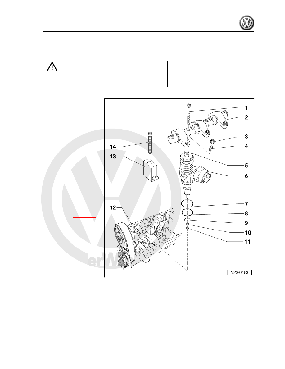
Always replace self-locking nuts and screws subject to angular

torque

1 - 20 Nm + 90°

❑ Replace after each re‐

moval.

2 - Rocker arm shaft

❑ With rocker arm.
❑ Remove and install

⇒ page 112

 .

3 - Self-locking nut
4 - Set screw

❑ Replace.

5 - Ball head pin

❑ Replace.

6 - Injectors

❑ Remove and install

⇒ page 112

 .

7 - Sealing ring

❑ Replace 

⇒ page 109

 .

8 - Sealing ring

❑ Replace 

⇒ page 109

 .

9 - Sealing ring

❑ Replace 

⇒ page 109

 .

10 - Heat insulation sealing

❑ Replace.

11 - Circlip
12 - Cylinder head
13 - Tensioning block
14 - 12 Nm +270°

❑ Replace after each re‐

moval.

1.6

Sealing ring for injectors - remove and

install

Special tools and workshop equipment required

Fox 2004 ➤

1. Maintaining the direct injection Diesel system    

109


Removal

– Remove carefully old rings from injector.
– Ensure that no burrs are formed on the ring seat in the oper‐

ation above.

1.6.2

Installation

Note

Always use the assembly sleeves to fit the rings. If the as‐

sembly sleeves are not used, the rings may be damaged.

Gradually introduce the rings with no coloured markings. Then

check that the rings are correctly positioned in their respective

grooves. Ring size decreases towards nozzle.

Prevent the rings from rolling when sliding them on. The rings

must not be twisted when seated on the injector.

– Pull the heat insulation cover with the fastening clip.
– Carefully clean the seating surfaces of the injector ring.
– Slide Assembly sleeve -T10056/1- to stop position on unit in‐

jector.

– Slide upper ring carefully towards assembly sleeve and into

injector seat.

– Remove assembly sleeve.

Fox 2004 ➤

110


– Slide intermediate ring carefully towards assembly sleeve and

into injector seat.

– Remove assembly sleeve.

– Slide Assembly sleeve -T10056/3- to stop position on unit in‐

jector.

– Slide lower ring carefully towards assembly sleeve and into

injector seat.

– Remove assembly sleeve.
– Install the heat insulation cover with the fastening clip.

Fox 2004 ➤

1. Maintaining the direct injection Diesel system    

111


Special tools and workshop

equipment required
♦ Support -VW 387-
♦ Multi-tooth Socket -3410-
♦ Special wrench, long reach

-T10054-

♦ Extractor -T10055-
♦ Torque wrench - 5 to 50 Nm

(enc. 1/2") -VAG 1331-

1.7.1

Removal

– Remove the upper cover of the mechanical distribution and

the cylinder head cover.

– Turn crankshaft until the cams of the injector to be removed

point upwards.

– Loosen self-locking nuts of set screws -1- and remove the

screws.

– Remove rocker arm securing bolts -2- (from outwards to in‐

wards) with Multi-tooth socket -3410- and remove rocker arm

shaft.

– Remove tensioning block securing bolts -3- with Special long

reach wrench, -T10054- , and remove the block.

– Remove injector connector by using a screwdriver. To avoid

inclination, support opposite side of connector with light finger

pressure.

– Check injector locations.

Fox 2004 ➤

112


Content   ..  26  27  28  29   ..