Volkswagen Fox (2004 year). Manual - part 24


  Index      Volkswagen     Volkswagen Fox - service repair manual 2004 year


Search            copyright infringement  


Content   ..  22  23  24  25   ..


Volkswagen Fox (2004 year). Manual - part 24


demister, must be off.

Check operation and power supply voltage
– Fold rear seat forwards.
– Remove fuel pump access cover.
– Briefly operate starting motor. The fuel pump operation must

be audible.

– Switch off ignition.
If fuel pump does not work:
– Remove 4-pin connector from the fuel pump flange.
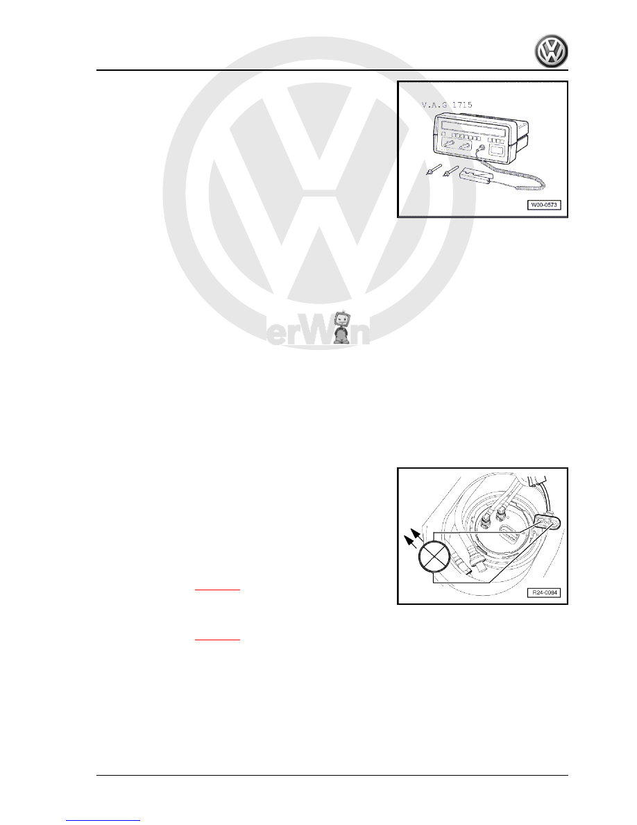
– Connect Test probe -VAG 1527B- to outer contacts of con‐

nector using adapter cables from -V.A.G 1594 - .

– Switch ignition on. The LED shall light ON for about 2 seconds.
If the LED does not light ON:
– Locate and repair cable interruption, according to the current

circuits scheme. ⇒ Current flow diagrams, Electrical fault find‐

ing and Fitting locations.

If the LED lights ON (power supply OK).
– Remove fuel pump 

⇒ page 91

 .

– Check if cables are connected between flange and fuel pump.
In case there is no cable interruption:
– Replace fuel pump 

⇒ page 91

 .

Check current consumption at fuel pump
– Remove 4-pin connector from the fuel pump flange.

Fox 2004 ➤

1. Fuel supply system components - remove and install     

93


tween the contacts -1- of the connector and fuel pump.

Note

The Multimeter -V.A.G 1715 - test probe can also be inserted be‐

tween the contact -1- connector and the fuel pump by using the

adapter cables of the Multimeter -V.A.G 1715 - .

– Connect contacts -4- of connector and fuel pump by using the

adapter cables from -V.A.G 1594 A- .

– Start engine and run at idle speed.
– Measure current at fuel pump. Specification: 6,3...7.8 A.
– If the values measured lie outside the specifications:
– Replace fuel pump 

⇒ page 91

 .

1.9

Accelerator mechanism - repair

1 - Support

❑ Remove and install ⇒ 

Rep. Gr.  46 .

2 - Connector

❑ Black, 6-pin.

3 - Accelerator pedal position

sensor -G79-

❑ Not adjustable.
❑ Accelerator pedal posi‐

tion sensor transmits

the pedal position to en‐

gine command unit.

❑ Remove feet rest area

cover to remove sensor.

4 - 10 Nm

Fox 2004 ➤

94


Special tools and workshop equipment required
♦ Pressure test equipment -VAS 5187-

♦ Torque wrench - 5 to 50 Nm ( enc. 1/2") -VAG 1331-

♦ Vehicle diagnosis, measurement and information system -

VAS 5051A/52- with Diagnostic cable (3 m) -VAS 5051/5-

Test conditions
• Coolant temperature at least 85 °C.
• Injectors must be in order.
• Fuel filter and pipes must not be blocked.
• The check valve in the fuel supply hose must be in order.
Test sequence
– Remove plug -arrow-.

Fox 2004 ➤

1. Fuel supply system components - remove and install     

95


Vehicle

self-diagnosis

. Then, select engine electronic control unit

with 

01 Engine electronic system

.

– Select function 

08 Read value block

.

– Select screen “2” via numeric keys (on keyboard) and confirm

with 

Q

 key.

– Read engine idle speed on field 1.
– Increase engine speed to 1,500 rpm.
– Check pressure on the pressure gauge. Specification: at least

3.5 bar.

– Press the 

 key.

– Select function 

06 End the test

 function key.

– Switch off ignition.
If the specification is not obtained:
– Replace auxiliary pump 

⇒ page 97

 .

Note

After removing pressure gauge unit, tighten plug at 25 Nm. Al‐

ways replace seal.

Fox 2004 ➤

96


Content   ..  22  23  24  25   ..