Toyota Prius Plug-in Hybrid (2023 year). Manual in english - page 37
 

  Index      Toyota     Toyota Prius Plug-in Hybrid (2023 year). Manual in english


Search            copyright infringement  


Content      ..     35      36      37      38     ..


Toyota Prius Plug-in Hybrid (2023 year). Manual in english - page 37


613

7-3. Do-it-yourself maintenance

7

M

a

in

te

nan
ce and

 ca

re

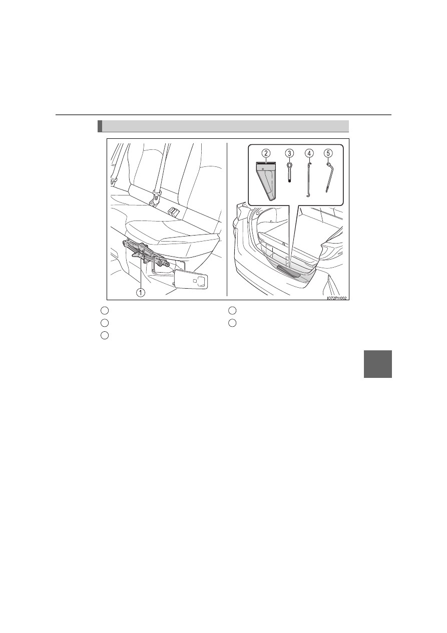
Location of the jack and tools

Jack
Tool bag
Towing eyelet

Jack handle
Wheel nut wrench

1
2
3

4
5

614

7-3. Do-it-yourself maintenance

WARNING

Using the tire jack

Observe the following precautions. 
Improper use of the tire jack may cause the vehicle to suddenly fall off the
jack, leading to death or serious injury.

Only use the tire jack that comes with this vehicle for replacing a tire. 
Do not use it on other vehicles, and do not use other tire jacks for replac-
ing tires on this vehicle.

Do not raise the vehicle while someone is inside.

Do not use the tire jack for any purpose other than replacing tires or install-
ing and removing tire chains.

Do not put any part of your body under the vehicle while it is supported by
the jack.

Do not start the hybrid system or drive the vehicle while the vehicle is sup-
ported by the jack.

When raising the vehicle, do not put an object on or under the jack.

Do not raise the vehicle to a height greater than that required to replace
the tire.

Use a jack stand if it is necessary to get under the vehicle.

When lowering the vehicle, make sure that there is no-one near the vehi-
cle. If there are people nearby, warn them vocally before lowering.

When removing the jack from the storage location

The jack may be hot due to heat from the charging equipment during or
after charging. Please use gloves when handling the jack. If it is touched
with bare hands, it may result in burns.

Put the jack properly in its jack point. 
(

P. 617)

615

7-3. Do-it-yourself maintenance

7

M

a

in

te

nan
ce and

 ca

re

Open the back door. (

P. 278)

Lift the deck under box cover
up and take out the tool bag.

Open the tool bag and then take out the jack handle and wheel nut
wrench.

After using the tools, stow them by reversing the steps listed.

Taking out the tools

1

2

3

616

7-3. Do-it-yourself maintenance

Pull the cover to disconnect the
tabs, and remove the cover.

Turn the portion 

 to loosen

the jack, and slowly take out the
jack.

Be careful when handling the jack,
as it may become hot depending
on conditions. (

P. 614)

If the portion   can not be loos-
ened, turn it using the jack handle.

Taking out the jack

1

2

A

A

617

7-3. Do-it-yourself maintenance

7

M

a

in

te

nan
ce and

 ca

re

Chock the tires.

Slightly loosen the wheel nuts
(one turn).

Turn the tire jack portion 

 by

hand until the center of the
recessed portion of the jack is
in contact with the center of the
jack point.

Replacing a tire

1

Tire position

Wheel chock positions

Front

Left-hand side

Behind the rear right-hand side tire

Right-hand side

Behind the rear left-hand side tire

Rear

Left-hand side

In front of the front right-hand side tire

Right-hand side

In front of the front left-hand side tire

2

Jack point

3

A

618

7-3. Do-it-yourself maintenance

Assemble the jack handle and
the wheel nut wrench as shown
in the illustration.

Raise the vehicle until the tire is
slightly raised off the ground.

Remove all the wheel nuts and
the tire.

When resting the tire on the
ground, place the tire so that the
wheel design faces up to avoid
scratching the wheel surface.

4

5

6

619

7-3. Do-it-yourself maintenance

7

M

a

in

te

nan
ce and

 ca

re

WARNING

Replacing a tire

Do not touch the disc wheels or the area around the brakes immediately
after the vehicle has been driven.
After the vehicle has been driven the disc wheels and the area around the
brakes will be extremely hot. Touching these areas with hands, feet or
other body parts while changing a tire, etc. may result in burns.

Failure to follow these precautions could cause the wheel nuts to loosen
and the tire to fall off, resulting in death or serious injury.
• Have the wheel nuts tightened with a torque wrench to 103 N•m

(10.5 kgf•m, 76 ft•lbf) as soon as possible after changing wheels.

• When installing a tire, only use wheel nuts that have been specifically

designed for that wheel.

• If there are any cracks or deformations in the bolt screws, nut threads or

bolt holes of the wheel, have the vehicle inspected by any authorized
Toyota retailer or Toyota authorized repairer, or any reliable repairer.

• When installing the wheel nuts, be sure to install the wheel nuts with the

tapered ends facing inward.

620

7-3. Do-it-yourself maintenance

Remove any dirt or foreign mat-
ter from the wheel contact sur-
face.

If foreign matter is on the wheel
contact surface, the wheel nuts
may loosen while the vehicle is in
motion, causing the tire to come
off.

Install the tire and loosely
tighten each wheel nut by hand
by approximately the same
amount.

Turn the wheel nuts until the wash-
ers come into contact with the disc
wheel.

Lower the vehicle.

Firmly tighten each wheel nut
two or three times in the order
shown in the illustration.

Tightening torque:

103 N•m (10.5 kgf•m, 76 ft•lbf)

Stow the tire jack and all tools.

Installing the tire

1

Washer

Disc wheel

2

3

4

5

621

7-3. Do-it-yourself maintenance

7

M

a

in

te

nan
ce and

 ca

re

Jack point

Storing the jack

The mark indicating the jack point is
stamped on the underside of the vehicle.

Fully insert the jack in the stowing posi-
tion, and turn the portion   to secure the
jack.

A

624

7-3. Do-it-yourself maintenance

WARNING

After using the tools and jack

Before driving, make sure all the tools and jack are securely in place in their
storage location to reduce the possibility of personal injury during a collision
or sudden braking.

NOTICE

When replacing the tires

When removing or fitting the wheels, tires or the tire pressure warning valve
and transmitter, contact any authorized Toyota retailer or Toyota authorized
repairer, or any reliable repairer as the tire pressure warning valve and
transmitter may be damaged if not handled correctly.

Handling the decorative resin parts (for vehicles equipped with 17-inch
wheels)

P. 570

625

7-3. Do-it-yourself maintenance

7

M

a

in

te

nan
ce and

 ca

re

Air conditioning filter

Turn the power switch off.

Confirm that the charging connector is not connected. Also, do not use the
Remote Air Conditioning System during the procedure.

Open the front passenger’s door.

By keeping the door open, unexpected operation of the Remote Air Condi-
tioning System can be prevent. (

P. 536)

Open the glove box and slide
off the damper.

Push in each side of the glove
box to disconnect the claws,
and then slowly and fully open
the glove box while supporting
it.

The air conditioning filter must be changed regularly to maintain
air conditioning efficiency.

Replacing the air conditioning filter

1

2

3

4

626

7-3. Do-it-yourself maintenance

With the glove box fully open,
slightly lift up the glove box and
pull toward the seat to detach
the bottom of the glove box.

Do not use excessive force if the
glove box does not detach when
lightly pulled. Instead, pull toward
the seat while slightly adjusting the
height of the glove box.

Remove the filter cover.

Unlock the filter cover.
Move the filter cover in the direction of the arrow, and then pull it
out of the claws.

Remove the filter case.

5

6

1
2

Left-hand drive vehicles

Right-hand drive vehicles

7

627

7-3. Do-it-yourself maintenance

7

M

a

in

te

nan
ce and

 ca

re

Remove the air conditioning fil-
ter from the filter case and
replace it with a new one.

The “

UP” marks shown on the fil-

ter should be pointing up.

When installing, reverse the steps listed.

Checking interval

Inspect and replace the air conditioning filter according to the maintenance
schedule. In dusty areas or areas with heavy traffic flow, early replacement
may be required. (For scheduled maintenance information, please refer to the
“Toyota Service Booklet” or “Toyota Warranty Booklet”.)

If air flow from the vents decreases dramatically

The filter may be clogged. Check the filter and replace if necessary.

8

WARNING

When replacing the air conditioning filter

Observe the following precautions. Failure to do so may result in the air
conditioning system operating during the procedure, possibly resulting in
injury.

Check that the charging connector is not connected
The air conditioning may operate due to the “Climate Prep” (

P. 166) or

“Traction Battery Cooler” (

P. 145) setting. (if equipped)

Do not use the Remote Air Conditioning System

9

628

7-3. Do-it-yourself maintenance

NOTICE

When using the air conditioning system

Make sure that a filter is always installed.
Using the air conditioning system without a filter may cause damage to the
system.

When removing the glove box

Always follow the specified procedure to remove the glove box (

P. 625). If

the glove box is removed without following the specified procedure, the
hinge of the glove box may become damaged.

To prevent damage to the filter cover

When moving the filter cover in the direc-
tion of arrow to release the fitting, pay
attention not to apply excessive force to
the claws. Otherwise, the claws may be
damaged. 

Left-hand drive vehicles

Right-hand drive vehicles

629

7-3. Do-it-yourself maintenance

7

M

a

in

te

nan
ce and

 ca

re

Wiper insert replacement

While securely supporting the
wiper blade connection by
hand, press the lock knob to
release the lock, and then pull
out the wiper blade.

Align the wiper blade with the
connecting portion of the wiper
arm, and then slide it in the
direction it was removed from.

After installing the wiper blade,
check that the connection is
locked.

When replacing the wiper insert, perform the following proce-
dure.

Windshield wiper blade removal and installation

1

2

630

7-3. Do-it-yourself maintenance

Pull the wiper insert until it pro-
trudes from the slit on the back
of the wiper blade.

Pull out the end of the wiper
insert from the slit, and then pull
out the rest of the wiper insert.

When installing a new wiper
insert, perform the procedure in
reverse.

After installation, check that the
end of the wiper insert is installed
all the way to the end of the cap.

Wiper insert replacement

1

2

3


Content      ..     35      36      37      38     ..