Toyota Tundra (2023 year). Manual in english - page 6
 

  Index      Toyota     Toyota Tundra (2023 year). Manual in english


Search            copyright infringement  


Content      ..     4      5      6      7     ..


Toyota Tundra (2023 year). Manual in english - page 6


95

2-1. Instrument cluster

2

Vehicle

 s

ta

tu

s information an

d in
dicat

or

s

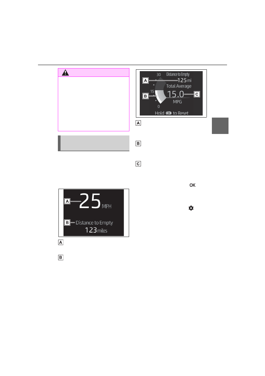
Select to display fuel consump-
tion data in various forms.

Speedometer display/Dis-
tance to empty (4.2-inch 
display type only)

Speedometer display

Displays the vehicle speed.

Distance to empty

Displays the driving range with 
remaining fuel. (

P.96)

Fuel economy

Use the displayed values as a ref-
erence only.

Distance to empty

Displays the driving range with 
remaining fuel. (

P.96)

Current fuel consumption

Displays instantaneous current fuel 
consumption.

Average fuel economy (after 
reset)

To reset the average fuel economy 
display, press and hold the 


meter control switch.

The average fuel economy dis-
play can be changed in 

(

P.98)

Average fuel economy (after 
start)

Displays the average fuel con-
sumption since engine start.

Average fuel economy (after 
refuel)

Displays the average fuel con-
sumption since the vehicle was 
refueled.

Eco Driving Indicator/Dis-
tance to empty

Eco Driving Indicator

WARNING

Caution for use while driving

For safety, avoid operating the 

meter control switch while driving 

as much as possible, and do not 

look continuously at the multi-

information display while driving. 

Stop the vehicle and operate the 

meter control switch. Failure to do 

so may cause a steering wheel 

operation error, resulting in an 

unexpected accident.

Content of driving infor-
mation

96

2-1. Instrument cluster

Eco Driving Indicator Zone 
Display

Suggests the Zone of Eco driving 
with current Eco driving ratio based 
on acceleration.

Eco driving ratio based on 
acceleration

If the acceleration exceeds the 
Zone of Eco driving, the right side 
of the Eco Driving Indicator Zone 
Display will illuminate.

Zone of Eco driving

Distance to empty

Displays the driving range with 
remaining fuel. (

P.96

)

Distance to empty

This distance is computed based 

on your average fuel consump-

tion. As a result, the actual dis-

tance that can be driven may differ 

from that displayed.

When only a small amount of fuel 

is added to the tank, the display 

may not be updated. When refuel-

ing, turn the engine switch to OFF. 

If the vehicle is refueled without 

turning the engine switch to OFF, 

the display may not be updated.

When “Refuel” is displayed, the 

remaining fuel amount is low and 

the distance that can be driven 

with the remaining fuel cannot be 

calculated. Refuel immediately.

Driving support system 
information

Select to display the operational 
status of the following systems:

LTA (Lane Tracing Assist) (if 
equipped) (

P.247)

Dynamic radar cruise control 
with full-speed range (if 
equipped) (

P.261)

Navigation system-linked 
display

Select to display the following 
navigation system-linked infor-
mation:

Route guidance to destination

Compass display (heading-up 
display)

Select to display the following 
navigation system-linked infor-
mation:

Route guidance to destination

Compass display (heading-up 
display)

Select to enable selection of an 

Driving support system 
information display (4.2-
inch display type only)

Navigation system-linked 
display (full LCD type 
only)

Audio system-linked dis-
play

97

2-1. Instrument cluster

2

Vehicle

 statu

s information an

d in
dicator

s

audio source or track on the 
meter using the meter control 
switches.

This menu icon can be set to be 
displayed/not displayed in 

.

Trailer brake

Displays trailer brake control 
status (

P.395) and trailer 

type

*

.

*

: To select the trailer, press and 

hold the 

 meter control switch. 

(

P.98)

Trailer Mode BSM

Displays trailer length

*

 and 

trailer blind spot status 
(

P.282).

*

: To select the trailer, press and 

hold the 

 meter control switch. 

(

P.98)

Pitch and roll gauges (4.2-
inch display type only)

Displays the longitudinal and lat-
eral inclination of the vehicle

Drive information

2 items that are selected using 
the “Drive Info Items” setting 
(average speed, distance and 
total time) can be displayed ver-
tically.
The displayed information 

changes according to the “Drive 
Info Type” setting (since the sys-
tem was started or between 
resets). (

P.98)

Use the displayed information as a 
reference only.
Following items will be displayed.

“Trip”

• “Average Speed”: Displays the 

average vehicle speed since 
engine start

*

• “Distance”: Displays the distance 

driven since engine start

*

• “Total Time”: Displays the elapsed 

time since engine start

*

*

: These items are reset each time 

the engine stops.

“Total”

• “Average Speed”: Displays the 

average vehicle speed since the 
display was reset

*

• “Distance”: Displays the distance 

driven since the display was 
reset

*

• “Total Time”: Displays the elapsed 

time since the display was reset

*

*

: To reset, display the desired item 

and press and hold the 

 meter 

control switch.

Tire inflation pressure

Displays inflation pressure of 
each tire.

Vehicle information dis-
play

98

2-1. Instrument cluster

Meter display settings that 
can be changed

Language

Select to change the language dis-
played.

Units

Select to change the units of mea-
sure displayed.

Meter Type (full LCD type 
only)

Select to change the main dial type 
to speedometer or tachometer.

/

 (Driving information 

display settings)

• Fuel economy display
Select to change the average fuel 
consumption display between after 
start/after reset/after refuel. 
(

P.95)

/

 (Audio settings)

Select to display/not display the 
audio system linked display.

/

 (Vehicle information 

display settings)

Select to change the displayed con-
tent of the following:
• Drive information type
Select to change the drive informa-
tion type display between after 
start/after reset.
• Drive information items
Select to set the first and second 
items of the drive information dis-
play to any of the following: aver-

age vehicle 
speed/distance/elapsed time.

Pop-up display

Select to enable/disable pop-up 
displays for each relevant system.

Multi-information display off

Select to turn the multi-information 
display off.
To turn the multi-information display 
on again, press any of the meter 
control switches.

Default setting

Select to reset the meter display 
settings to the default setting.

Changing settings of the 
trailer type

Trailer settings screen

Displays the name of the cur-
rently selected trailer or “No 
Trailer Selected” if a trailer 
has not yet been selected

Add a new trailer or select an 
existing saved trailer

• Maximum of 10 trailers can be 

saved.

• Select the trailer name, length, 

hitch type, brake type and num-
ber of axles.

• The parameters which can be set 

depend on which of the trailer 

Settings display

99

2-1. Instrument cluster

2

Vehicle

 statu

s information an

d in
dicator

s

systems are installed on the vehi-
cle. (Trailer Brake Controller, 
Trailer Backup Guide and Trailer 
Mode BSM)

Deselect the currently 
selected trailer

• Used when a 4-pin trailer connec-

tor has been disconnected. (4-pin 
trailer connector disconnection 
cannot be automatically detected 
by Trailer Brake Controller)

Edit the parameters of a 
saved trailer (name, length, 
hitch type, brake type and 
number of axles)

• The parameters which can be 

edited depend on which of the 
trailer systems are installed on 
the vehicle (Trailer Brake Control-
ler, Trailer Backup Guide and 
Trailer Mode BSM)

Delete a saved trailer

Trailer detail screen

Displays the name of the cur-
rent trailer which is being 
added or edited.

Change the name of the 
trailer.

Change the hitch type of the 
trailer between ball hitch 

(conventional), gooseneck or 
fifth wheel. Note that goose-
neck and fifth wheel trailers 
are not supported for some 
features (Trailer Backup 
Guide and Trailer Mode 
BSM)

Change the length of the 
trailer. If the exact length is 
not listed, round up the actual 
length of the trailer to the 
closest available value.

“Auto” length detection can also be 
selected.

Change the number of axles.

Change the brake type (elec-
tric or electric over hydraulic) 
and weight of the trailer, or 
turn trailer brakes off for that 
trailer.

Save the trailer information

If there are any errors with the 
trailer values, re-select the value or 
delete and re-save the trailer. If the 
error continues, contact your Toy-
ota dealer.

Vehicle functions and set-
tings that can be changed

P.567

Suspension of the settings dis-

play

Some settings cannot be changed 

while driving. When changing set-

tings, park the vehicle in a safe 

place.

If a warning message is displayed, 

operation of the settings display 

will be suspended.

100

2-1. Instrument cluster

Select to display warning mes-
sages and measures to be 
taken if a malfunction is 
detected. (

P.520)

Stop & Start system opera-
tion time (after start)/status 
notification

Displays the current amount of time 
the engine has been stopped by the 
operation of the Stop & Start sys-
tem.
Also shows the status of the Stop & 
Start system with a pop-up display. 
(

P.279)

Stop & Start system settings

The length of time of the Stop & 
Start system will operate when the 
“A/C” switch of the air conditioning 
system is on can be set to 2 differ-
ent levels in 

 of the multi-infor-

mation display. (

P.279)

WARNING

Cautions during setting up 

the display

If the engine is running when 

changing the display settings, 

ensure that the vehicle is parked 

in a place with adequate ventila-

tion. In a closed area such as a 

garage, exhaust gases including 

harmful carbon monoxide (CO) 

may collect and enter the vehicle. 

This may lead to death or a seri-

ous health hazard.

NOTICE

During setting up the display

To prevent battery discharge, 

ensure that the engine is running 

while setting up the display fea-

tures.

Warning message display

Stop & Start system infor-
mation

101

2-1. Instrument cluster

2

Vehicle

 statu

s information an

d in
dicator

s

*

: If equipped

Illustrations used in this text are intended as examples, and may differ from 
the image that is actually displayed by the head-up display.

Driving support system status (if equipped)/navigation system-
linked display area (

P.103)

Shift position display/RSA (Road Sign Assist) display area (if 
equipped) (

P.206, 258)

Vehicle speed display

Eco Driving Indicator/Outside temperature display area (

P.104)

Head-up display will operate 

when

The engine switch is in ON.

When using the head-up dis-

play

The head-up display may seem 

dark or hard to see when viewed 

through sunglasses, especially 

polarized sunglasses. Adjust the 

brightness of the head-up display or 

remove your sunglasses.

Street name display

Only street names which are 

included in the map data will be dis-

played.

Head-up display

*

The head-up display projects a variety of driving-related infor-
mation and the operating state of the driving support systems 
on the windshield.

System components

102

2-1. Instrument cluster

Select 

 on the multi-informa-

tion display (

P.569) and then 

“HUD Main”.

Enabling/disabling the 
head-up display

Press the 

 meter control 

switch to enable/disable the 
head-up display.

Changing the head-up dis-
play settings

Press and hold the 

 meter 

control switch to change the fol-
lowing settings:

Brightness and vertical posi-
tion of the head-up display

Select to adjust the brightness or 
vertical position of the head-up dis-
play.

Display content

Select to change the display 
between the following:
• No content
• Eco Driving Indicator

Select to enable/disable the 
following items:

• Route guidance to destination
• Driving support system display (if 

equipped)

• Compass (heading-up display)
• Audio system operation status

Display angle

Select to adjust the angle of the 

WARNING

When using the head-up dis-

play

Check that the position and 

brightness of the head-up dis-

play image does not interfere 

with safe driving. Incorrect 

adjustment of the image’s posi-

tion or brightness may obstruct 

the driver’s view and lead to an 

accident, resulting in death or 

serious injury.

Do not continuously look at the 

head-up display while driving as 

you may fail to see pedestrians, 

objects on the road, etc., ahead 

of the vehicle.

NOTICE

Head-up display projector

Do not place any drinks near 

the head-up display projector. If 

the projector gets wet, electrical 

malfunctions may result.

Do not place anything on or put 

stickers onto the head-up dis-

play projector.

Doing so could interrupt head-

up display indications.

Do not touch the inside of the 

head-up display projector or 

thrust sharp edges or the like 

into the projector.

Doing so could cause mechani-

cal malfunctions.

Using the head-up display

103

2-1. Instrument cluster

2

Vehicle

 s

ta

tu

s information an

d in
dicat

or

s

head-up display.

Enabling/disabling of the head-

up display

If the head-up display is disabled, it 

will remain disabled when the 

engine switch is turned off then back 

to ON.

Display brightness

The brightness of the head-up dis-
play can be adjusted on 

 of the 

multi-information display. Also, it is 
automatically adjusted according to 
the ambient brightness.

Driving support system sta-
tus display

Displays the operational status 

of the following systems:

LTA (Lane Tracing Assist) (if 
equipped) (

P.247)

Dynamic radar cruise control 
with full-speed range (if 
equipped) (

P.261)

Details of content displayed on the 
head-up display may differ from 
that displayed on the multi-informa-
tion display. For details, refer to the 
explanation of each system.

Navigation system-linked 
display area

Displays the following items 
which are linked to the naviga-
tion system:

Street name

Route guidance to destination

Compass (heading-up dis-
play)

Pop-up displays for the following 
systems will be displayed when 
necessary:

Driving support systems

Displays a warning/sugges-
tion/advice message or the 
operating state of a relevant 
system.

PCS (Pre-Collision System) 
(if equipped) (

P.235)

LTA (Lane Tracing Assist) (if 
equipped) (

P.247)

PKSB (Parking Support 
Brake) (if equipped) (

P.302)

WARNING

Caution for changing settings 

of the head-up display

If the engine is running when 

changing the display 

settings, ensure that the vehicle 

is parked in a place with adequate 

ventilation. In a closed area such 

as a garage, exhaust gases 

including harmful carbon monox-

ide (CO) may collect and enter 

the vehicle. This may lead to 

death or a serious health hazard.

NOTICE

When changing the settings 

of the head-up display

To prevent battery discharge, 

ensure that the engine is running 

while changing the settings of the 

head-up display.

Driving support system 
status/navigation system-
linked display area

Pop-up display

104

2-1. Instrument cluster

Brake Override System 
(

P.176)

Drive-Start Control (

P.181)

Details of content displayed on the 
head-up display may differ from 
that displayed on the multi-informa-
tion display. For details, refer to the 
explanation of each system.

/

 icons

These icons are linked to the 
multi-information display

: Master warning icon

Displayed when a warning mes-
sage is displayed on the multi-infor-
mation display. (

P.520)

: Information icon

Displayed when an advice pop-up 
display is displayed on the multi-
information display.

Warning message

Some warning messages are 
displayed when necessary, 
according to certain conditions.

Details of content displayed on the 
head-up display may differ from 
that displayed on the multi-informa-
tion display.

Audio system operation 
status

Displayed when an audio 
remote control switch on the 
steering wheel is operated.

Hands-free system status

Displayed when the hands-free 
system is operated.

When a pop-up display is dis-

played

When a pop-up display is displayed, 

a current display may no longer be 

displayed. In this case, the display 

will return after the pop-up display 

disappears.

Eco Driving Indicator

Eco Driving Indicator Zone 
Display

Eco driving ratio based on 
acceleration

Zone of Eco driving

Displayed content is the same as 
that displayed on the multi-informa-
tion display (Eco Driving Indicator). 
For details, refer to P.95.

Outside temperature dis-
play

Displayed when the engine 
switch is turned to ON or when 
the low outside temperature 
indicator is flashing.

Outside temperature display

When the ambient temperature is 

approximately 37°F (3°C) or 

Eco Driving Indicator/Out-
side temperature display

105

2-1. Instrument cluster

2

Vehicle

 statu

s information an

d in
dicator

s

lower, the low outside temperature 

indicator will flash for approxi-

mately 10 seconds and the out-

side temperature display will turn 

off. In this case, the display will be 

displayed again when the outside 

temperature becomes approxi-

mately 41°F (5°C) or higher.

In the following situations, the cor-

rect outside temperature may not 

be displayed, or the display may 

take longer than normal to 

change:

• When stopped, or driving at low 

speeds (less than 16 mph [25 

km/h])

• When the outside temperature 

has changed suddenly (at the 

entrance/exit of a garage, tunnel, 

etc.)

When “--” is displayed, the system 

may be malfunctioning. Take your 

vehicle to your Toyota dealer.

Current fuel consumption 
screen

1

Select 

 on the main 

menu.

2

Select “Trip information”.

If a screen other than “Current” is 
displayed, select “Current”.

Average vehicle speed since 
the engine was started.

Trip range

Elapsed time since the 

Fuel consumption 

information

Fuel consumption informa-
tion can be displayed on the 
multimedia system.

Consumption

106

2-1. Instrument cluster

engine was started.

Fuel consumption in the past 
15 minutes

Current fuel consumption

Resetting the consumption 
data

Use the displayed average fuel 
consumption as a reference. The 
image is an example only, and may 
vary slightly from actual conditions.

History fuel consumption 
screen

1

Select 

 on the main 

menu.

2

Select “Trip information”.

If a screen other than “History” is 
displayed, select “History”.

Latest fuel consumption

Best recorded fuel consump-

tion

Previous fuel consumption 
record

Resetting the history data

Updating the latest fuel con-
sumption data

Use the displayed average fuel 
consumption as a reference. The 
image is an example only, and may 
vary slightly from actual conditions.

Updating the history data

Update the average fuel consump-

tion by selecting “Update” to mea-

sure the current fuel consumption 

again.

Resetting the data

The fuel consumption data can be 

deleted by selecting “Clear data”.

Trip range

Displays the estimated maximum 

distance that can be driven with the 

quantity of fuel remaining.
As a result, the actual distance that 

can be driven may differ from that 

displayed.

107

3

3

Before 

driving

Before driving

3-1. Key information

Keys ............................

108

3-2. Opening, closing and 

locking the doors and 
tailgate

Side doors...................

111

Power running boards.

115

Tailgate........................

118

Power bed step ...........

124

Smart key system .......

126

3-3. Adjusting the seats

Front seats ..................

131

Rear seats...................

132

Driving position memory

..................................

135

Head restraints............

139

3-4. Adjusting the steering 

wheel and mirrors

Steering wheel ............

142

Inside rear view mirror

144

Digital Rear-view Mirror

145

Outside rear view mirrors

..................................

156

3-5. Opening, closing the win-

dows and moon roof

Power windows ...........

161

Power back window ....

164

Moon roof....................

165

Panoramic moon roof..

168

108

3-1. Key information

3-1.Key information

The following keys are provided 
with the vehicle.

Electronic keys

• Operating the smart key system 

(

P.126)

• Operating the wireless remote 

control function (

P.109)

Mechanical keys

Key number plate

When riding in an aircraft

When bringing an electronic key 

onto an aircraft, make sure you do 

not press any buttons on the elec-

tronic key while inside the aircraft 

cabin. If you are carrying an elec-

tronic key in your bag, etc., ensure 

that the buttons are not likely to be 

pressed accidentally. Pressing a 

button may cause the electronic key 

to emit radio waves that could inter-

fere with the operation of the air-

craft.

Electronic key battery depletion

The standard battery life is 1 to 2 

years.

If the battery becomes low, an 

alarm will sound in the cabin and a 

message will be shown on the 

multi-information display when the 

engine is stopped.

To reduce key battery depletion 

when the electronic key is to not 

be used for long periods of time, 

set the electronic key to the bat-

tery-saving mode. (

P.127)

As the electronic key always 

receives radio waves, the battery 

will become depleted even if the 

electronic key is not used. The fol-

lowing symptoms indicate that the 

electronic key battery may be 

depleted. Replace the battery 

when necessary.

• The smart key system or the wire-

less remote control does not oper-

ate.

• The detection area becomes 

smaller.

• The LED indicator on the key sur-

face does not turn on.

To avoid serious deterioration, do 

not leave the electronic key within 

3 ft. (1 m) of the following electri-

cal appliances that produce a 

magnetic field:

• TVs

• Personal computers

• Cellular phones, cordless phones 

and battery chargers

• Recharging cellular phones or 

cordless phones

• Table lamps

• Induction cookers

Replacing the battery

P.492

Confirmation of the number of 

registered keys

The number of keys already regis-

tered to the vehicle can be con-

firmed. Ask your Toyota dealer for 

details.

If “A New Key has been Regis-

tered Contact Your Dealer for 

Details” is shown on the multi-

information display

This message will be displayed 

each time the driver’s door is 

opened when the doors are 

unlocked from the outside for 

Keys

The keys

109

3-1. Key information

3

Before 

driving

approximately 10 days after a new 

electronic key has been registered.

If this message is displayed but you 

have not had a new electronic key 

registered, ask your Toyota dealer to 

check if an unknown electronic key 

(other than those in your posses-

sion) has been registered.

The electronic keys are 
equipped with the following 
wireless remote control:

Locks the doors and the tail-
gate (

P.111)

Unlocks the doors and the 
tailgate (

P.111)

Opens the windows

*1

 and the 

moon roof

*1, 2

 or the pan-

oramic moon roof

*1, 2


(

P.111)

Opens the tailgate and 
deploys power bed step

*1, 2

(

P.119, 125)

Sounds the alarm

*1

:This setting must be customized 

at your Toyota dealer.

*2

:If equipped

NOTICE

To prevent key damage

Do not drop the keys, subject 

them to strong shocks, or bend 

them.

Do not expose the keys to high 

temperatures for a long period 

of time.

Do not get the keys wet or wash 

them in an ultrasonic washer, 

etc.

Do not attach metallic or mag-

netic materials to the keys or 

place the keys close to such 

materials.

Do not disassemble the keys.

Do not attach a sticker or any-

thing else to the surface of the 

electronic key.

Do not place the keys near 

objects that produce magnetic 

fields, such as TVs, audio sys-

tems and induction cookers, or 

medical electrical equipment, 

such as low-frequency therapy 

equipment.

Carrying the electronic key 

on your person

Carry the electronic key 3.9 in. 

(10 cm) or more away from elec-

tric appliances that are turned on. 

Radio waves emitted from electric 

appliances within 3.9 in. (10 cm) 

of the electronic key may interfere 

with the key, causing the key to 

not function properly.

In case of a smart key system 

malfunction or other key-

related problems

P.535

When an electronic key is lost

P.534

Wireless remote control

110

3-1. Key information

Theft deterrent panic mode

When 

 is pressed for longer 

than about one second, an alarm 
will sound intermittently and the 
vehicle lights will flash to deter any 
person from trying to break into or 
damage your vehicle.
To stop the alarm, press any button 

on the electronic key.

To take out the mechanical key, 
slide the release lever   and 
take the key out.

The mechanical key can only be 
inserted in one direction, as the key 
only has grooves on one side. If the 
key cannot be inserted in a lock cyl-
inder, turn it over and re-attempt to 
insert it.
After using the mechanical key, 
store it in the electronic key. Carry 
the mechanical key together with 
the electronic key. If the electronic 
key battery is depleted or the entry 
function does not operate properly, 
you will need the mechanical key. 
(

P.535)

When required to leave the 

vehicle’s key with a parking 

attendant

Remove the mechanical key for 

your own use and provide the atten-

dant with the electronic key only.

If you lose your mechanical 

keys

P.534

If a wrong key is used

The key cylinder rotates freely, iso-

lated from the internal mechanism.

Using the mechanical key


Content      ..     4      5      6      7     ..