Toyota RAV4 Prime (2023 year). Manual in english - page 32
 

  Index      Toyota     Toyota RAV4 Prime (2023 year). Manual in english


Search            copyright infringement  


Content      ..     30      31      32      33     ..


Toyota RAV4 Prime (2023 year). Manual in english - page 32


517

7-3. Do-it-yourself maintenance

7

Maintena

nce
 a

nd ca

re

 and 

.

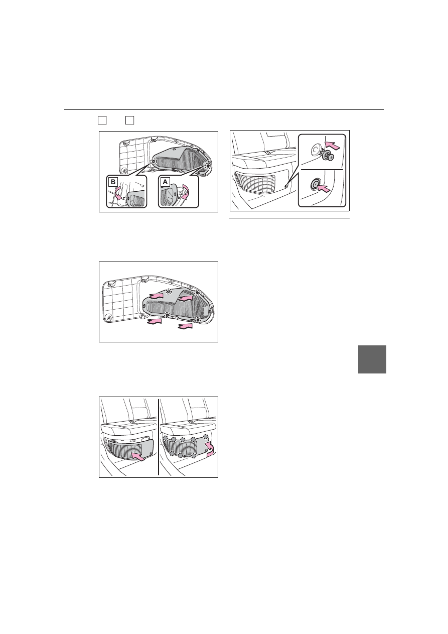
Engage the 4 center claws to install 

the filter.
Make sure that the filter is not 

crooked or deformed when install-

ing it.

7

Install the air intake vent 
cover.

Insert the tab of the cover as shown 

in the illustration and push the 

cover to engage the 8 claws.

8

Install the clip.

Cleaning the air intake vent

Dust in the air intake vent may 

interfere with the cooling of the 

DC/DC converter. If the cooling 

performance/capacity of the 

DC/DC converter becomes lim-

ited, the 12-volt battery may dis-

charge. Inspect and clean the air 

intake vent periodically.

Improper handling of the air intake 

vent cover and filter may result in 

damage to them. If you have any 

concerns about cleaning the filter, 

contact your Toyota dealer.

If “Maintenance required for 

DCDC converter cooling parts 

See Owner’s Manual” is shown 

on the multi-information display

If this warning message is shown 

on the multi-information display, 

remove the air intake vent cover 

and clean the filter. (

P.516)

After cleaning the air intake vent, 

start the hybrid system and check 

that the warning message is no 

longer shown.

It may take approximately 20 min-

utes after the hybrid system is 

started until the warning message 

disappears. If the warning mes-

sage does not disappear, have 

the vehicle inspected by your 

Toyota dealer.

B

A

518

7-3. Do-it-yourself maintenance

WARNING

When cleaning the air intake 

vent

Before cleaning the air intake 

vent, make sure to turn the 

power switch off to stop the 

hybrid system.

Do not use water or other liq-

uids to clean the air intake vent. 

If water is applied to the DC/DC 

converter or other components, 

a malfunction or fire may occur.

NOTICE

When cleaning the air intake 

vent

When cleaning the air intake vent, 

make sure to only use a vacuum 

to suck out dust and clogs. If a 

compressed air blow gun, etc. is 

used to blow out dust and clogs, 

the dust or clogs may be pushed 

into the air intake vent, which may 

affect the performance of the 

DC/DC converter and cause a 

malfunction.

To prevent damage to the 

vehicle

Do not allow water or foreign 

matter to enter the air intake 

vent when the cover is 

removed.

Carefully handle the removed 

filter so that it will not be dam-

aged. If the filter is damaged, 

have it replaced with a new filter 

by your Toyota dealer.

Make sure to reinstall the filter 

and cover to their original posi-

tions after cleaning.

Do not install anything to the air 

intake vent other than the exclu-

sive filter for this vehicle or use 

the vehicle without the filter 

installed.

If “Maintenance required for 

DCDC converter cooling parts 

See Owner’s Manual” is 

shown on the multi-informa-

tion display

If the vehicle is continuously 

driven with the warning message 

(indicating that the cooling perfor-

mance/capacity of the DC/DC 

converter may become limited) 

displayed, the DC/DC converter 

may malfunction. If the warning 

message is displayed, clean the 

air intake vent immediately.

519

7-3. Do-it-yourself maintenance

7

Maintena

nce
 a

nd ca

re

Windshield wiper blade 
removal and installation

1

While holding the hook por-
tion 

 of the wiper arm, first 

lift up the driver side, and 
then lift up the passenger 
side.

When returning the wiper arms to 

their original positions, first lower 

the passenger side, and then lower 

the driver side.

2

Lift the stopper using a flat-
head screwdriver as shown 
in the illustration.

To prevent damage to the wiper 

arm, protect the tip of the screw-

driver with a rag.

3

Slide the wiper blade to 
remove it from the wiper arm.

When installing, reverse the steps 

listed.

Wiper insert replacement

1

Pull the wiper insert to 
remove the claw of the wiper 
blade from the stopper, and 
pull out the wiper insert.

Wiper insert replace-

ment

When replacing the wiper 
insert, perform the following 
procedure to operate each 
wiper.

Windshield wipers

A

520

7-3. Do-it-yourself maintenance

Stopper

Claw

2

Remove the 2 metal plates 
from the wiper insert pulled 
out, and install the plates to a 
new wiper insert.

Make sure that the cutout location 

and warp direction of the metal 

blades are same as the original.

3

Install the wiper insert to the 
wiper blade from the side 
without the stopper.

4

Secure the stopper of the 
wiper insert with the claw of 
the wiper blade.

1

Lift up the rear window wiper 
arm head cap.

2

Move the wiper blade until a 
click sound can be heard and 

the claw detaches, and then 
remove the wiper blade from 
the wiper arm.

3

Pull the wiper insert out past 
the stopper on the wiper 
blade, and then continue to 
pull until it is completely 
removed.

Lightly grasp between the claws of 

the wiper blade to allow the wiper 

insert to lift up, making it easier to 

remove.

4

Remove the 2 metal plates 
from the old wiper insert and 

Rear window wiper

A

B

521

7-3. Do-it-yourself maintenance

7

Maintena

nce
 a

nd ca

re

install them to the replace-
ment wiper insert.

5

Insert the wiper insert starting 
from the claw at the center of 
the wiper blade. Pass the 
wiper insert through the 3 
claws so that it sticks out 
from the stopper, and then 
pass the wiper insert through 
the final remaining claw.

Applying a small amount of washer 

fluid to the wiper insert can make it 

easier to insert the claws into the 

grooves.

6

Check that the wiper blade 
claws are fitted in the 
grooves of the wiper insert.

If the wiper blade claws are not fit-

ted in the grooves of the wiper 

insert, grasp the wiper insert and 

slide it back and forth multiple times 

to insert the claws into the grooves.
Lightly lift up the center of the wiper 

insert to make the rubber easier to 

slide.

7

When installing a wiper 
blade, reverse the procedure 
in step 

1

.

After installing the wiper blade, 

check that the connection is locked.

Wiper blade and wiper insert 

handling

Improper handling may result in 

damage to the wiper blades or wiper 

insert. If you have any concerns 

about replacing the wiper blades or 

wiper insert yourself, contact your 

Toyota dealer.

NOTICE

When lifting the windshield 

wipers

When raising the wiper arms off 

the windshield, lift up the driver 

side first, and then lift up pas-

senger side. When returning the 

wipers to their original position, 

return the passenger side first.

Do not lift a windshield wiper by 

the wiper blade. Otherwise, the 

wiper blade may be deformed.

Do not operate the wiper lever 

when the windshield wipers are 

lifted. Otherwise, the wind-

shield wipers may contact the 

hood, possibly resulting in dam-

age to the windshield wipers 

and/or hood.

522

7-3. Do-it-yourself maintenance

If the key battery is depleted

The following symptoms may occur:

The smart key system and wire-

less remote control will not func-

tion properly.

The operational range will be 

reduced.

Prepare the following before 
replacing the battery:

Flathead screwdriver

Small flathead screwdriver

Lithium battery CR2450

Use a CR2450 lithium battery

Batteries can be purchased at 

your Toyota dealer, local electrical 

appliance shops or camera stores.

Replace only with the same or 

equivalent type recommended by 

the manufacturer.

Dispose of used batteries accord-

ing to the local laws.

NOTICE

To prevent damage

Be careful not to damage the 

claws when replacing the wiper 

insert.

After the wiper blade is removed 

from the wiper arm, place a 

cloth, etc., between the rear 

window and wiper arm to pre-

vent damage to the rear win-

dow.

Be sure not to pull excessively 

on the wiper insert or deform its 

metal plates.

Electronic key battery

Replace the battery with a 
new one if it is depleted.

Items to prepare

523

7-3. Do-it-yourself maintenance

7

Maintena

nce
 a

nd ca

re

1

Release the lock and remove 
the mechanical key.

2

Remove the key cover.

Use a screwdriver of an appropriate 

size. Forcedly prying may cause 

the cover damaged.
To prevent damage to the key, 

cover the tip of the flathead screw-

driver with a rag.

3

Remove the depleted battery 
using a small flathead screw-
driver.

When removing the cover, the elec-

tronic key module may stick to the 

cover and the battery may not be 

visible. In this case, remove the 

electronic key module in order to 

remove the battery.
Insert a new battery with the “+” ter-

minal facing up.

4

When installing, reverse the 
steps listed.

Replacing the battery

WARNING

Battery precautions

Observe the following precau-

tions.
Failure to do so may result in 

death or serious injury.

Do not swallow the battery. 

Doing so may cause chemical 

burns.

A coin battery or button battery 

is used in the electronic key. If a 

battery is swallowed, it may 

cause severe chemical burns in 

as little as 2 hours and may 

result in death or serious injury.

Keep away new and removed 

batteries from children.

If the cover cannot be firmly 

closed, stop using the electronic 

key and stow the key in the 

place where children cannot 

reach, and then contact your 

Toyota dealer.

If you accidentally swallow a 

battery or put a battery into a 

part of your body, get emer-

gency medical attention imme-

diately.

524

7-3. Do-it-yourself maintenance

1

Turn the power switch off.

Confirm that the charging connec-

tor is not connected. Also, do not 

use the Remote Air Conditioning 

System during the procedure.

2

Open the fuse box cover.

Engine compartment: Type A 
fuse box

Push claws 

 and 

 to com-

pletely release the lock, and then lift 
up the cover.

Engine compartment: Type B 
fuse box

Push claws 

 and 

 to com-

pletely release the lock, and then lift 
up the cover.

WARNING

To prevent battery explosion 

or leakage of flammable liq-

uid or gas

Replace the battery with a new 

battery of the same type. If a 

wrong type of battery is used, it 

may explode.

Do not expose batteries to 

extremely low pressure due to 

high altitude or extremely high 

temperatures.

Do not burn, break or cut a bat-

tery.

NOTICE

When replacing the battery

Use a flathead screwdriver of 

appropriate size. Applying exces-

sive force may deform or damage 

the cover.

For normal operation after 

replacing the battery

Observe the following precautions 

to prevent accidents:

Always work with dry hands.

Moisture may cause the battery 

to rust.

Do not touch or move any other 

component inside the remote 

control.

Do not bend either of the battery 

terminals.

Checking and replac-

ing fuses

If any of the electrical com-
ponents do not operate, a 
fuse may have blown. If this 
happens, check and replace 
the fuses as necessary.

Checking and replacing 
fuses

A

B

A

B

525

7-3. Do-it-yourself maintenance

7

Maintena

nce
 a

nd ca

re

Left side instrument panel

Remove the lid.

Right side luggage compart-
ment

Open the deck board. (

P.442)

Push claw 

 and 

 to com-

pletely release the lock, and then lift 
up the cover.

3

Remove the fuse.

Only type A fuse can be removed 

using the pullout tool.

4

Check if the fuse is blown.

Replace the blown fuse with a new 

fuse of an appropriate amperage 

rating. The amperage rating can be 

found on the fuse box lid.

Type A

Normal fuse

Blown fuse

Type B

Normal fuse

Blown fuse

A

B

A

B

A

B

526

7-3. Do-it-yourself maintenance

Type C

Normal fuse

Blown fuse

After a fuse is replaced

When installing the lid, make sure 

that the tab is installed securely.

If the lights do not turn on even 

after the fuse has been replaced, 

a bulb may need replacement. 

(

P.528)

If the replaced fuse blows again, 

have the vehicle inspected by 

your Toyota dealer.

If there is an overload in a cir-

cuit

The fuses are designed to blow, 

protecting the wiring harness from 

damage.

When replacing an electronic 

component, such as a lights, 

etc.

Toyota recommends that you use 

genuine Toyota products designed 

for this vehicle. Because certain 

electronic components are con-

nected to circuits designed to pre-

vent overload, non-genuine parts or 

parts not designed for this vehicle 

may be unusable.

A

B

WARNING

To prevent system break-

downs and vehicle fire

Observe the following precau-

tions.

Failure to do so may cause dam-

age to the vehicle, and possibly a 

fire or injury.

Never use a fuse of a higher 

amperage rating than that indi-

cated, or use any other object in 

place of a fuse.

Always use a genuine Toyota 

fuse or equivalent.

Never replace a fuse with a 

wire, even as a temporary fix.

Do not modify the fuses or fuse 

boxes.

NOTICE

Before replacing fuses

Have the cause of electrical over-

load determined and repaired by 

your Toyota dealer as soon as 

possible.

To prevent damage to the 

engine compartment fuse box 

cover

When opening the fuse box, com-

pletely release the claw locks 

before lifting up the cover. Other-

wise, the claws may be damaged.

527

7-3. Do-it-yourself maintenance

7

Maintena

nce
 a

nd ca

re

Adjustment bolt A

Adjustment bolt B

Make sure the vehicle has a 
full tank of gasoline and the 
area around the headlight is 
not deformed.

Park the vehicle on level 
ground.

Make sure the tire inflation 
pressure is at the specified 
level.

Have someone sit in the 
driver’s seat.

Bounce the vehicle several 
times.

1

Using a Phillips-head screw-
driver, turn bolt A in either 
direction.
Remember the turning direc-
tion and the number of turns.

2

Turn bolt B the same number 
of turns and in the same 
direction as step 

1

.

If the headlight cannot be adjusted 

using this procedure, take the vehi-

cle to your Toyota dealer to adjust 

the headlight aim.

Headlight aim

Vertical movement adjust-
ing bolts

Before checking the head-
light aim

A

B

Adjusting the headlight 
aim

528

7-3. Do-it-yourself maintenance

Check the wattage of the light 
bulb to be replaced. (

P.586)

Rear

Rear turn signal lights

Back-up lights

Lights that need to be 
replaced by your Toyota 
dealer

Headlights

Front turn signal lights

Daytime running lights and 
parking lights

Front side marker lights

LED accessory lights (if 
equipped)

Side turn signal lights

Tail lights

Stop lights

Rear side marker lights

High mounted stoplight

License plate lights

Outer foot lights (if equipped)

LED lights

The lights other than the following 

lights each consist of a number of 

LEDs. If any of the LEDs burn out, 

take your vehicle to your Toyota 

dealer to have the light replaced.

Rear turn signal lights

Back-up lights

Condensation build-up on the 

inside of the lens

Temporary condensation build-up 

on the inside of the light lens does 

not indicate a malfunction. Contact 

your Toyota dealer for more infor-

mation in the following situations:

Large drops of water have built up 

on the inside of the lens.

Water has built up inside the light.

When replacing an electronic 

component, such as a lights, 

etc.

P.526

Light bulbs

You may replace the follow-
ing bulbs by yourself. The 
difficulty level of replace-
ment varies depending on 
the bulb. If necessary bulb 
replacement seems difficult 
to perform, contact your 
Toyota dealer.
For more information about 
replacing other light bulbs, 
contact your Toyota dealer.

Preparing for light bulb 
replacement

Bulb location

A

B

529

7-3. Do-it-yourself maintenance

7

Maintena

nce
 a

nd ca

re

Rear turn signal lights

1

Open the back door and 
remove the cover.

2

Remove the screws and 
remove the unit.

Remove the lamp assembly by pull-

ing it directly backward from the 

rear of the vehicle.

3

Turn the bulb base counter-
clockwise.

4

Remove the light bulb.

5

Install a new light bulb then 
install the bulb base to the 
light unit by inserting it and 
turning the bulb base clock-
wise.

6

Align the grooves on the light 
unit with the claws, and insert 
the light unit straight so that 
the pin on the light unit fit into 
the hole.

Confirm that the light unit is com-

Replacing light bulb

530

7-3. Do-it-yourself maintenance

pletely secured.

7

Reinstall the screws.

8

Reinstall the cover.

Back-up lights

1

Open the back door and 
remove the cover.

To prevent damage to the cover, 

protect the tip of the screwdriver 

with a rag.

2

Turn the bulb base counter-
clockwise.

Remove the cord from the clip 

before turning the bulb base.

3

Remove the light bulb.

531

7-3. Do-it-yourself maintenance

7

Maintena

nce
 a

nd ca

re

4

Install a new light bulb.

5

Install the bulb base to the 
light unit by inserting it and 
turning the bulb base clock-
wise.

Secure the cord with the clip back 

again after installing the bulb base.

6

Reinstall the cover.

WARNING

Replacing light bulb

Turn off the light. Do not attempt 

to replace the bulb immediately 

after turning off the light. 

The bulb become very hot and 

may cause burns.

Do not touch the glass portion 

of the light bulb with bare 

hands. When it is unavoidable 

to hold the glass portion, use 

and hold with a clean dry cloth 

to avoid getting moisture and 

oils on the bulb. 

Also, if the bulb is scratched or 

dropped, it may blow out or 

crack.

Fully install light bulb and any 

parts used to secure it. Failure 

to do so may result in heat dam-

age, fire, or water entering the 

light unit. This may damage the 

light or cause condensation to 

build up on the lens.

Do not attempt to repair or dis-

assemble light bulbs, connec-

tors, electric circuits or 

component parts.

Doing so may result in death or 

serious injury due to electric 

shock.

To prevent damage or fire

Make sure bulb is fully seated 

and locked.

Check the wattage of the bulb 

before installing to prevent heat 

damage.

533

8

8

Whe

n tr

ouble

 a

rises

When trouble arises

8-1. Essential information

Emergency flashers ....

534

If your vehicle has to be 

stopped in an emergency

..................................

535

If the vehicle is submerged 

or water on the road is ris-
ing .............................

536

8-2. Steps to take in an emer-

gency

If your vehicle needs to be 

towed.........................

538

If you think something is 

wrong ........................

540

If a warning light turns on or 

a warning buzzer sounds

..................................

541

If a warning message is dis-

played........................

552

If you have a flat tire....

557

If the hybrid system will not 

start ...........................

564

If you lose your keys ...

566

If the fuel filler door cannot 

be opened .................

566

If the electronic key does 

not operate properly ..

567

If the 12-volt battery is dis-

charged .....................

569

If your vehicle overheats

..................................

574

If the vehicle becomes 

stuck..........................

578


Content      ..     30      31      32      33     ..