Toyota Corolla Cross (2023 year). Manual in english - page 23
368
6-3. Do-it-yourself maintenance
*
: If equipped
■
If the key battery is depleted
The following symptoms may occur:
●
The smart key system (if
equipped) and wireless remote
control will not function properly.
●
The operational range will be
reduced.
Flathead screwdriver
Small flathead screwdriver
Lithium battery CR2016 (vehi-
cles without a smart key sys-
tem) or CR2450 (vehicles with
a smart key system)
■
Use a CR2016 or CR2450 lith-
ium battery
●
Batteries can be purchased at
your Toyota dealer, local electrical
appliance shops or camera stores.
●
Replace only with the same or
equivalent type recommended by
the manufacturer.
●
Dispose of used batteries accord-
ing to local laws.
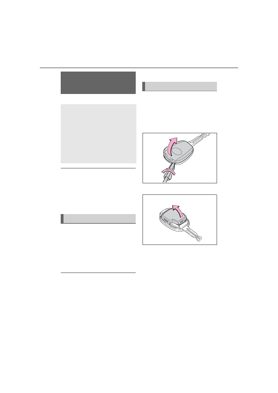
Vehicles without a smart key
system
1
Remove the cover.
To prevent damage to the key,
cover the tip of the flathead screw-
driver with a rag.
2
Remove the module.
3
Open the case cover using a
coin protected with tape etc.
and remove the depleted bat-
tery.
Insert a new battery with the “+” ter-
Wireless remote con-
trol/electronic key bat-
tery
*
Replace the battery with a
new one if it is depleted.
As the key may be damaged
if the following procedure is
not performed properly, it is
recommended that key bat-
tery replacement be per-
formed by your Toyota
dealer.
Items to prepare
Replacing the battery