Toyota Corolla Hybrid (2022 year). Manual in english - page 14
 

  Index      Toyota     Toyota Corolla Hybrid (2022 year). Manual in english


Search            copyright infringement  


Content      ..     12      13      14      15     ..


Toyota Corolla Hybrid (2022 year). Manual in english - page 14


225

4-5. Using the driving support systems

4

Dr

iv

ing

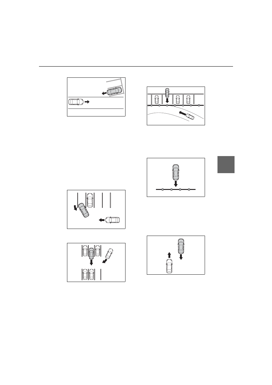
angle parking spot

When towing a trailer

When there is a significant differ-

ence in height between your vehi-

cle and the vehicle that enters the 

detection area

When a sensor or the area around 

a sensor is extremely hot or cold

If the suspension has been modi-

fied or tires of a size other than 

specified are installed

If the front of the vehicle is raised 

or lowered due to the carried load

When turning while backing up

When a vehicle turns into the 

detection area

Situations in which the system 

may operate even if there is no 

possibility of a collision

Instances of the RCTA function 

unnecessary detecting a vehicle 

and/or object may increase in the 

following situations:

When the parking space faces a 

street and vehicles are being 

driven on the street

When the distance between your 

vehicle and metal objects, such as 

a guardrail, wall, sigh, or parked 

vehicle, which may reflect electri-

cal waves toward the rear of the 

vehicle, is short

When equipment that may 

obstruct a sensor is installed, such 

as a towing eyelet, bumper pro-

tector (an additional trim strip, 

etc.), bicycle carrier, or snow plow

When a vehicle passes by the 

side of your vehicle

When a detected vehicle turns 

while approaching the vehicle

226

4-5. Using the driving support systems

When there are spinning objects 

near your vehicle such as the fan 

of an air conditioning unit

When water is splashed or 

sprayed toward the rear bumper, 

such as from a sprinkler

Moving objects (flags, exhaust 

fumes, large rain droplets or 

snowflakes, rain water on the road 

surface, etc.)

When the distance between your 

vehicle and a guardrail, wall, etc., 

that enters the detection area is 

short

Gratings and gutters

When a sensor or the area around 

a sensor is extremely hot or cold

If the suspension has been modi-

fied or tires of a size other than 

specified are installed

If the front of the vehicle is raised 

or lowered due to the carried load

The rear view image is dis-
played when the shift lever is in 
R and the power switch is in ON.

Rear view monitor sys-

tem

Audio

The rear view monitor sys-
tem assists the driver by 
displaying an image of the 
view behind the vehicle with 
fixed guide lines on the 
screen while backing up, for 
example while parking.

The screen illustrations 
used in this text are 
intended as examples, and 
may differ from the image 
that is actually displayed on 
the screen.

Audio Plus

Owners of models equipped 
with a navigation/multime-
dia system should refer to 
the “NAVIGATION AND 
MULTIMEDIA SYSTEM 
OWNER’S MANUAL”.

System overview

227

4-5. Using the driving support systems

4

Dr

iv

ing

The rear view monitor system 

will be deactivated when the 
shift lever is shifted to any posi-
tion other than R.

Screen description

The rear view monitor system screen will be displayed if the shift 
lever is shifted to R while the power switch is in ON.

Vehicle width extension guide line

Displays a guide path when the vehicle is being backed straight up. The 
displayed width is wider than the actual vehicle width.

Vehicle center guide line

This line indicates the estimated vehicle center on the ground.

Distance guide line

Displays a point approximately 1.5 ft. (0.5 m) (red) from the edge of the 
bumper.

Distance guide line

Displays a point approximately 3 ft. (1 m) (blue) from the edge of the 
bumper.

Using the rear view monitor system

228

4-5. Using the driving support systems

Area displayed on screen

Corners of bumper

The rear view monitor system 
displays an image of the view 
from the bumper of the rear area 
of the vehicle.
The image adjustment proce-
dure for the rear view monitor 
system screen is the same as 
the procedure for adjusting the 
screen. (

P.262)

The area displayed on the 
screen may vary according to 
vehicle orientation conditions.

Objects which are close to 
either corner of the bumper or 
under the bumper cannot be 
displayed.

The camera uses a special 
lens. The distance of the 
image that appears on the 
screen differs from the actual 
distance.

Items which are located 
higher than the camera may 
not be displayed on the moni-
tor.

Rear view monitor system 
camera

The camera for the rear view 
monitor system is located as 
shown in the illustration.

Using the camera

If dirt or foreign matter (such as 
water droplets, snow, mud etc.) is 
adhering to the camera, it cannot 
transmit a clear image. In this case, 
flush it with a large quantity of water 
and wipe the camera lens clean 
with a soft and wet cloth.

Differences between the 
screen and the actual road

The distance guide lines and the 
vehicle width guide lines may 
not actually be parallel with the 
dividing lines of the parking 
space, even when they appear 

Rear view monitor system 
precautions

229

4-5. Using the driving support systems

4

Dr

iv

ing

to be so. Be sure to check visu-
ally.
The distances between the vehi-
cle width guide lines and the left 
and right dividing lines of the 
parking space may not be equal, 
even when they appear to be 
so. Be sure to check visually.
The distance guide lines give a 
distance guide for flat road sur-
faces. In any of the following sit-
uations, there is a margin of 
error between the fixed guide 
lines on the screen and the 
actual distance/course on the 
road.

When the ground behind the 
vehicle slopes up sharply

The distance guide lines will appear 
to be closer to the vehicle than the 
actual distance. Because of this, 
objects will appear to be farther 

away than they actually are. In the 
same way, there will be a margin of 
error between the guide lines and 
the actual distance/course on the 
road.

When the ground behind the 
vehicle slopes down sharply

The distance guide lines will appear 
to be further from the vehicle than 
the actual distance. Because of 
this, objects will appear to be closer 
than they actually are. In the same 
way, there will be a margin of error 
between the guide lines and the 
actual distance/course on the road.

When any part of the vehicle 
sags

230

4-5. Using the driving support systems

A margin of error

When any part of the vehicle sags 
due to the number of passengers or 
the distribution of the load, there is 
a margin of error between the fixed 
guide lines on the screen and the 
actual distance/course on the road.

When approaching 
three-dimensional objects

The distance guide lines are dis-
played according to flat surfaced 
objects (such as the road). It is 
not possible to determine the 
position of three-dimensional 
objects (such as vehicles) using 
the distance guide lines. When 
approaching a three-dimen-
sional object that extends out-
ward (such as the flatbed of a 
truck), be careful of the follow-
ing.

Vehicle width guide lines

Vehicle width guide lines

Visually check the surroundings 
and the area behind the vehicle. In 
the case shown below, the truck 
appears to be outside of the vehicle 
width guide lines and the vehicle 
does not look as if it hits the truck. 
However, the rear body of the truck 
may actually cross over the vehicle 
width guide lines. In reality if you 
back up as guided by the vehicle 
width guide lines, the vehicle may 
hit the truck.

Distance guide lines

231

4-5. Using the driving support systems

4

Dr

iv

ing

Visually check the surroundings 
and the area behind the vehicle. On 
the screen, it appears that a truck is 
parking at point 

. However, in 

reality if you back up to point 

you will hit the truck. On the screen, 
it appears that 

 is closest and 


is farthest away. However, in reality, 
the distance to 

 and 

 is the 

same, and 

 is farther than 


and 

.

If you notice any symptoms

If you notice any of the following symptoms, refer to the likely cause 
and the solution, and re-check.
If the symptom is not resolved by the solution, have the vehicle 
inspected by your Toyota dealer.

Things you should know

232

4-5. Using the driving support systems

Symptom

Likely cause

Solution

The image is difficult to 
see

The vehicle is in a dark 
area

The temperature 
around the lens is 
either high or low

The outside tempera-
ture is low

There are water drop-
lets on the camera

It is raining or humid

Foreign matter (mud 
etc.) is adhering to the 
camera

Sunlight or headlights 
are shining directly 
into the camera

The vehicle is under 
fluorescent lights, 
sodium lights, mer-
cury lights etc.

If this happens due to 
these causes, it does 
not indicate a malfunc-
tion. Back up while visu-
ally checking the 
vehicle’s surroundings. 
(Use the monitor again 
once conditions have 
been improved.) The 
procedure for adjusting 
the picture quality of the 
rear view monitor sys-
tem is the same as the 
procedure for adjusting 
the screen. (

P.262)

The image is blurry

Dirt or foreign matter 
(such as water droplets, 
snow, mud etc.) is 
adhering to the camera.

Flush the camera with a 
large quantity of water 
and wipe the camera 
lens clean with a soft 
and wet cloth.

The image is out of 
alignment

The camera or sur-
rounding area has 
received a strong 
impact.

Have the vehicle 
inspected by your Toy-
ota dealer.

The fixed guide lines 
are very far out of 
alignment

The camera position is 
out of alignment.

Have the vehicle 
inspected by your Toy-
ota dealer.

The vehicle is tilted 
(there is a heavy load 
on the vehicle, tire 
pressure is low due to 
a tire puncture, etc.)

The vehicle is used on 
an incline.

If this happens due to 
these causes, it does 
not indicate a malfunc-
tion.
Back up while visually 
checking the vehicle’s 
surroundings.

233

4-5. Using the driving support systems

4

Dr

iv

ing

WARNING

When using the rear view 

monitor system

The rear view monitor system is a 

supplemental device intended to 

assist the driver when backing up. 

When backing up, be sure to visu-

ally check all around the vehicle 

both directly and using the mirrors 

before proceeding. Observe the 

following precautions to avoid an 

accident that could result in death 

or serious injuries.

Never depend on the rear view 

monitor system entirely when 

backing up. The image and the 

position of the guide lines dis-

played on the screen may differ 

from the actual state. Use cau-

tion, just as you would when 

backing up any vehicle.

Be sure to back up slowly, 

depressing the brake pedal to 

control vehicle speed.

The instructions given are only 

guide lines. When and how 

much to turn the steering wheel 

will vary according to traffic con-

ditions, road surface condi-

tions, vehicle condition, etc. 

when parking. It is necessary to 

be fully aware of this before 

using the rear view monitor sys-

tem.

When parking, be sure to check 

that the parking space will 

accommodate your vehicle 

before maneuvering into it.

Do not use the rear view moni-

tor system in the following 

cases:

• On icy or slick road surfaces, or 

in snow

• When using tire chains or emer-

gency tires

• When the trunk is not closed 

completely

• On roads that are not flat or 

straight, such as curves or 

slopes

In low temperatures, the screen 

may darken or the image may 

become faint. The image could 

distort when the vehicle is mov-

ing, or you may become unable 

to see the image on the screen. 

Be sure to visually check all 

around the vehicle both directly 

and using the mirrors before 

proceeding.

If the tire sizes are changed, the 

position of the fixed guide lines 

displayed on the screen may 

change.

The camera uses a special lens. 

The distances between objects 

and pedestrians that appear in 

the image displayed on the 

screen will differ from the actual 

distances. (

P.228)

NOTICE

How to use the camera

The rear view monitor system 

may not operate properly in the 

following cases.

• If the back of the vehicle is hit, 

the position and mounting angle 

of the camera may change.

• As the camera has a water 

proof construction, do not 

detach, disassemble or modify 

it. This may cause incorrect 

operation.

234

4-5. Using the driving support systems

Each time the switch is pressed, the 
system changes between power 
mode, normal mode and Eco drive 
mode.

1

Normal mode

Provides an optimal balance of fuel 
economy, quietness, and dynamic 
performance. Suitable for normal 
driving.

2

Power mode

Controls the hybrid system to pro-
vide quick, powerful acceleration. 
Making it suitable for when agile 
driving response is desired, such 
as when driving on roads with many 
curves.
When the power mode is selected, 
power mode indicator comes on.

3

Eco drive mode

Helps the driver accelerate in an 
eco-friendly manner and improve 
fuel economy through moderate 
throttle characteristics and by con-

• When cleaning the camera lens, 

flush the camera with a large 

quantity of water and wipe it 

with a soft and wet cloth. 

Strongly rubbing the camera 

lens may cause the camera lens 

to be scratched and unable to 

transmit a clear image.

• Do not allow organic solvent, 

car wax, window cleaner or 

glass coating to adhere to the 

camera. If this happens, wipe it 

off as soon as possible.

• If the temperature changes rap-

idly, such as when hot water is 

poured on the vehicle in cold 

weather, the system may not 

operate normally.

• When washing the vehicle, do 

not apply intensive bursts of 

water to the camera or camera 

area. Doing so may result in the 

camera malfunctioning.

Do not expose the camera to 

strong impact as this could 

cause a malfunction. If this hap-

pens, have the vehicle 

inspected by your Toyota dealer 

as soon as possible.

Driving mode select 

switch

The driving modes can be 
selected to suit driving con-
dition.

Selecting a drive mode

235

4-5. Using the driving support systems

4

Dr

iv

ing

trolling the operation of the air con-
ditioning system (heating/cooling).
When the Eco drive mode is 
selected, Eco drive mode indicator 
comes on.

Operation of the air condition-

ing system in Eco drive mode

Eco drive mode controls the heat-

ing/cooling operations and fan 

speed of the air conditioning system 

to enhance fuel efficiency. To 

improve air conditioning perfor-

mance, perform the following opera-

tions:

Turn off eco air conditioning mode 

(

P.384)

Adjust the fan speed (

P.383)

Turn off Eco drive mode

The driving mode after turning 

the power switch off

The driving mode will not be 

changed automatically until the 

switch is pressed, even if the power 

switch is turned off.

ECB (Electronically Con-
trolled Brake System)

The electronically controlled 
system generates braking force 
corresponding to the brake 
operation

ABS (Anti-lock Brake Sys-
tem)

Helps to prevent wheel lock 
when the brakes are applied 
suddenly, or if the brakes are 
applied while driving on a slip-
pery road surface

Brake assist

Generates an increased level of 
braking force after the brake 
pedal is depressed when the 
system detects a panic stop sit-
uation

Driving assist systems

To keep driving safety and 
performance, the following 
systems operate automati-
cally in response to various 
driving situations. Be 
aware, however, that these 
systems are supplementary 
and should not be relied 
upon too heavily when oper-
ating the vehicle.

Summary of the driving 
assist systems

236

4-5. Using the driving support systems

VSC (Vehicle Stability Con-
trol)

Helps the driver to control skid-
ding when swerving suddenly or 
turning on slippery road sur-
faces.

Enhanced VSC (Enhanced 
Vehicle Stability Control)

Provides cooperative control of 
the ABS, TRAC, VSC and EPS.
Helps to maintain directional 
stability when swerving on slip-
pery road surfaces by con-
trolling steering performance.

TRAC (Traction Control)

Helps to maintain drive power 
and prevent the drive wheels 
from spinning when starting the 
vehicle or accelerating on slip-
pery roads

Active Cornering Assist 
(ACA)

Helps to prevent the vehicle 
from drifting to the outer side by 
performing inner wheel brake 
control when attempting to 
accelerate while turning

Hill-start assist control

Helps to reduce the backward 
movement of the vehicle when 
starting on an uphill

EPS (Electric Power Steer-
ing)

Employs an electric motor to 
reduce the amount of effort 
needed to turn the steering 
wheel.

The Secondary Collision 
Brake

When the SRS airbag sensor 
detects a collision and the sys-
tem operates, the brakes and 
brake lights are automatically 
controlled to reduce the vehicle 
speed and help reduce the pos-
sibility of further damage due to 
a secondary collision.

When the TRAC/VSC/ABS sys-

tems are operating

The slip indicator light will flash 

while the TRAC/VSC/ABS systems 

are operating.

Disabling the TRAC system

If the vehicle gets stuck in mud, dirt 

or snow, the TRAC system may 

reduce power from the hybrid sys-
tem to the wheels. Pressing 

 to 

turn the system off may make it eas-

ier for you to rock the vehicle in 

order to free it.
To turn the TRAC system off, quickly 
press and release 

.

The “Traction Control Turned OFF” 
will be shown on the multi-informa-
tion display.

Press 

 again to turn the system 

back on.

237

4-5. Using the driving support systems

4

Dr

iv

ing

Turning off both TRAC and VSC 

systems

To turn the TRAC and VSC systems 
off, press and hold

 for more 

than 3 seconds while the vehicle is 

stopped.
The VSC OFF indicator light will 
come on and the “Traction Control 
Turned OFF” will be shown on the 
multi-information display.

*

Press

 again to turn the system 

back on.

*

: PCS will also be disabled (only 

Pre-Collision warning is avail-
able). The PCS warning light will 
come on and a message will be 
displayed on the multi-information 
display. (

P.191)

When the message is dis-

played on the multi-information 

display showing that TRAC has 
been disabled even if 

 has 

not been pressed

TRAC is temporary deactivated. If 

the information continues to show, 

contact your Toyota dealer.

Operating conditions of 

hill-start assist control

When the following four conditions 

are met, the hill-start assist control 

will operate:

The shift lever is in a position 

other than P or N (when starting 

off forward/backward on an 

upward incline)

The vehicle is stopped

The accelerator pedal is not 

depressed

The parking brake is not engaged

Automatic system cancelation 

of hill-start assist control

The hill-start assist control will turn 

off in any of the following situations:

The shift lever is shifted to P or N.

The accelerator pedal is 

depressed

The parking brake is engaged

2 seconds at maximum elapsed 

after the brake pedal is released

Sounds and vibrations caused 

by the ABS, brake assist, VSC, 

TRAC and hill-start assist con-

trol systems

A sound may be heard from the 

engine compartment when the 

brake pedal is depressed repeat-

edly, when the hybrid system is 

started or just after the vehicle 

begins to move. This sound does 

not indicate that a malfunction has 

occurred in any of these systems.

Any of the following conditions 

may occur when the above sys-

tems are operating.

None of these indicates that a 

malfunction has occurred.

• Vibrations may be felt through the 

vehicle body and steering.

• A motor sound may be heard also 

after the vehicle comes to a stop.

ECB operating sound

ECB operating sound may be heard 

in the following cases, but it does 

not indicate that a malfunction has 

occurred.

Operating sound heard from the 

engine compartment when the 

brake pedal is operated.

Motor sound of the brake system 

heard from the front part of the 

vehicle when the driver’s door is 

opened.

238

4-5. Using the driving support systems

Operating sound heard from the 

engine compartment when one or 

two minutes passed after the stop 

of the hybrid system.

Active Cornering Assist opera-

tion sounds and vibrations

When the Active Cornering Assist is 

operated, operation sounds and 

vibrations may be generated from 

the brake system, but this is not a 

malfunction.

EPS operation sound

When the steering wheel is oper-

ated, a motor sound (whirring 

sound) may be heard. This does not 

indicate a malfunction.

Automatic reactivation of TRAC 

and VSC systems

After turning the TRAC and VSC 

systems off, the systems will be 

automatically re-enabled in the fol-

lowing situations:

When the power switch is turned 

off

If only the TRAC system is turned 

off, the TRAC will turn on when 

vehicle speed increases

If both the TRAC and VSC sys-

tems are turned off, automatic 

re-enabling will not occur when 

vehicle speed increases.

Operating conditions of Active 

Cornering Assist

The system operates when the fol-

lowing occurs.

TRAC/VSC can operate

The driver is attempting to accel-

erate while turning

The system detects that the vehi-

cle is drifting to the outer side

The brake pedal is released

Reduced effectiveness of the 

EPS system

The effectiveness of the EPS sys-

tem is reduced to prevent the sys-

tem from overheating when there is 

frequent steering input over an 

extended period of time. The steer-

ing wheel may feel heavy as a 

result. Should this occur, refrain 

from excessive steering input or 

stop the vehicle and turn the hybrid 

system off. The EPS system should 

return to normal within 10 minutes.

Secondary Collision Brake 

operating conditions

The system operates when the SRS 

airbag sensor detects a collision 

while the vehicle is in motion.

However, the system does not oper-

ate in any of the following situations.

The vehicle speed is below 6 mph 

(10 km/h)

Components are damaged

Secondary Collision Brake 

automatic cancellation

The system is automatically can-

celed in any of the following situa-

tions.

The vehicle speed drops below 

approximately 6 mph (10 km/h)

A certain amount of time elapses 

during operation

The accelerator pedal is 

depressed a large amount

WARNING

The ABS does not operate 

effectively when

The limits of tire gripping perfor-

mance have been exceeded 

(such as excessively worn tires 

on a snow covered road).

The vehicle hydroplanes while 

driving at high speed on wet or 

slick roads.

239

4-5. Using the driving support systems

4

Dr

iv

ing

WARNING

Stopping distance when the 

ABS is operating may exceed 

that of normal conditions

The ABS is not designed to 

shorten the vehicle’s stopping dis-

tance. Always maintain a safe dis-

tance from the vehicle in front of 

you, especially in the following sit-

uations:

When driving on dirt, gravel or 

snow-covered roads

When driving with tire chains

When driving over bumps in the 

road

When driving over roads with 

potholes or uneven surfaces

TRAC/VSC may not operate 

effectively when

Directional control and power may 

not be achievable while driving on 

slippery road surfaces, even if the 

TRAC/VSC system is operating. 

Drive the vehicle carefully in con-

ditions where stability and power 

may be lost.

Active Cornering Assist does 

not operate effectively when

Do not overly rely on Active 

Cornering Assist. Active Corner-

ing Assist may not operate 

effectively when accelerating 

down slopes or driving on slip-

pery road surfaces.

When Active Cornering Assist 

frequently operates, Active Cor-

nering Assist may temporarily 

stop operating to ensure proper 

operation of the brakes, TRAC 

and VSC.

Hill-start assist control does 

not operate effectively when

Do not overly rely on hill-start 

assist control. Hill-start assist 

control may not operate effec-

tively on steep inclines and 

roads covered with ice.

Unlike the parking brake, 

hill-start assist control is not 

intended to hold the vehicle sta-

tionary for an extended period 

of time. Do not attempt to use 

hill-start assist control to hold 

the vehicle on an incline, as 

doing so may lead to an acci-

dent.

When the TRAC/ABS/VSC is 

activated

The slip indicator light flashes. 

Always drive carefully. Reckless 

driving may cause an accident. 

Exercise particular care when the 

indicator light flashes.

When the TRAC/VSC systems 

are turned off

Be especially careful and drive at 

a speed appropriate to the road 

conditions. As these are the sys-

tems to help ensure vehicle stabil-

ity and driving force, do not turn 

the TRAC/VSC systems off 

unless necessary.

Replacing tires

Make sure that all tires are of the 

specified size, brand, tread pat-

tern and total load capacity. In 

addition, make sure that the tires 

are inflated to the recommended 

tire inflation pressure level.
The ABS, TRAC and VSC sys-

tems will not function correctly if 

different tires are installed on the 

vehicle.

Contact your Toyota dealer for fur-

ther information when replacing 

tires or wheels.

240

4-5. Using the driving support systems

WARNING

Handling of tires and the sus-

pension

Using tires with any kind of prob-

lem or modifying the suspension 

will affect the driving assist sys-

tems, and may cause a system to 

malfunction.

Secondary Collision Brake

Do not rely solely upon the Sec-

ondary Collision Brake. This sys-

tem is designed to help reduce 

the possibility of further damage 

due to a secondary collision, how-

ever, that effect changes accord-

ing to various conditions. Overly 

relying on the system may result 

in death or serious injury.


Content      ..     12      13      14      15     ..